![]()
Reprint from THE "HOW-TO-DO-IT" BOOKSCARPENTRY FOR BOYS
|
I - II - III - IV - V - VI - VII - VIII - IX - X - XI - XII - XIII - XIV - XV - XVI - XVII - XVIII - XIX - XX - XXI
CHAPTER V
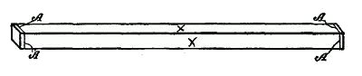
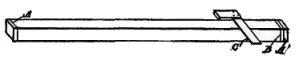
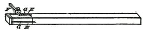
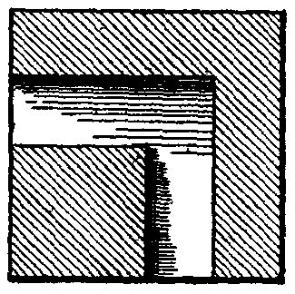
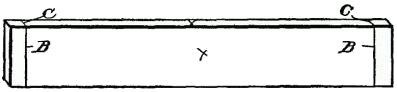
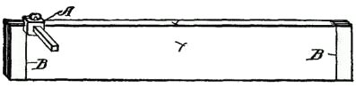
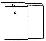
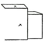
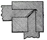
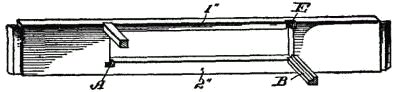
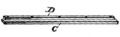
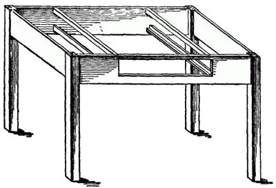
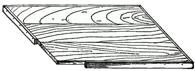
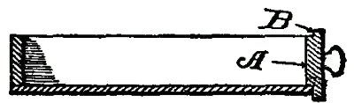
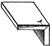
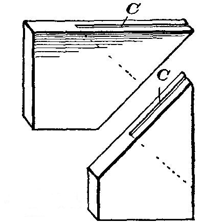
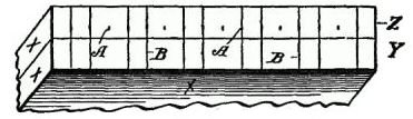
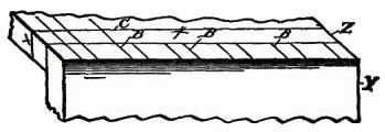
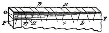
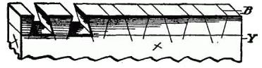
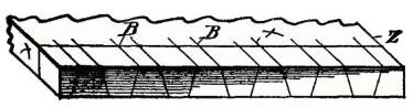
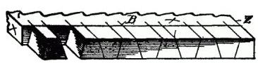
HOW WORK IS LAID OUTConcrete Examples of Work.—A concrete example of doing any work is more valuable than an abstract statement. For this purpose I shall direct the building of a common table with a drawer in it and show how the work is done in detail. For convenience let us adopt the Mission style, with a top 36" × 42" and the height 30". The legs should be 2" × 2" and the top 1", dressed. The material should be of hard wood with natural finish, or, what is better still, a soft wood, like birch, which may be stained a dark brown, as the Mission style is more effective in dark than in light woods. Framework.—As we now know the sizes, the first thing is to build the framework. The legs should be dressed square and smoothed down with the fore plane to make them perfectly straight. Now, lay out two mortises at the upper end of each leg. Follow the illustrations to see how this is done. Laying Out the Legs.—Fig. 27 shows a leg with square cross marks (A) at each end. These marks indicate the finished length of the leg. You will also see crosses on two sides. These indicate what is called the "work sides." The work sides are selected because they are the finest surfaces on the leg. The Length of the Mortises.—Then take a small try square (Fig. 28) and add two cross lines (B, C) on each of the inner surfaces, the second line (B) one-half inch from the finish line (A), and the other line (C) seven inches down from the line (A). The side facing boards, hereafter described, are seven inches wide. When this has been done for all the legs, prepare your gage (Fig. 29) to make the mortise scribe, and, for convenience in illustrating, the leg is reversed. If the facing boards are 1" thick, and the tenons are intended to be ½" thick, the first scribe line (E) should be ½" from the work side, because the shoulder on the facing board projects out ¼", and the outer surface of the facing board should not be flush with the outer surface of the leg. The second gage line (F) should be 1" from the work side. The Mortises.—When the mortises have been made they will appear as shown in the enlarged cross section of the leg (Fig. 30), the total depth of each mortise being 1½". The depth of this mortise determines for us the length of the tenons on the facing boards. The Facing Boards.—These boards are each 1 inch thick and 7 inches wide. As the top of the table is 42 inches long, and we must provide an overhang, say of 2 inches, we will first take off 4 inches for the overhang and 4 inches for the legs, so that the length of two of the facing boards, from shoulder to shoulder, must be 34 inches; and the other two facing boards 28 inches. Then, as we must add 1½ inches for each tenon, two of the boards will be 37 inches long and two of them 31 inches long. The illustration (Fig. 31) shows a board marked with the cross lines (B) at each end for the end of the tenons, or the extreme ends of the boards. The Tenons.—Do not neglect first to select the work side and the working edge of the board. The outer surface and the upper edges are the sides to work from. The cheekpiece (A) of the gage must always rest against the working side. The cross marks (B, C) should be made with the point of a sharp knife, and before the small back saw is used on the cross-cuts the lines (B), which indicate the shoulders, should be scored with a sharp knife, as shown in Fig. 33. This furnishes a guide for the saw, and makes a neat finish for the shoulder. Tools Used.—The back saw is used for cutting the tenon, and the end of the board appears as shown in the enlarged Fig. 34. Two things are now necessary to complete the tenons. On the upper or work edge of each board use the gage to mark off a half-inch slice, and then cut away the flat side of the tenon at the end, on its inner surface, so it will appear as shown in Fig. 35. Chamfered Tenons.—The object of these chamfered or beveled tenons is to permit the ends to approach each other closely within the mortise, as shown in the assembled parts (Fig. 36). The Frame Assembled.—The frame is now ready to assemble, but before doing so a drawer opening and supports should be made. The ends of the supports may be mortised into the side pieces or secured by means of gains. Mortises and tenons are better. The Drawer Supports.—Take one of the side-facing boards (Fig. 37) and cut a rectangular opening in it. This opening should be 4 inches wide and 18 inches long, so placed that there is 1 inch of stock at the upper margin and 2 inches of stock at the lower margin of the board. At each lower corner make a mortise (A), so that one side of the mortise is on a line with the margin of the opening, and so that it extends a half inch past the vertical margin of the opening. You can easily cut a gain (B) in a strip, or, as in Fig. 38, you may use two strips, one (C) an inch wide and a half inch thick, and on this nail a strip (D) along one margin. This forms the guide and rest for the drawer. At the upper margin of the opening is a rebate or gain (E) at each corner, extending down to the top line of the drawer opening, into which are fitted the ends of the upper cross guides. The Table Frame.—When the entire table frame is assembled it will have the appearance shown in Fig. 39, and it is now ready for the top. The Top.—The top should be made of three boards, either tongued and grooved, or doweled and glued together. In order to give a massive appearance, and also to prevent the end grain of the boards from being exposed, beveled strips may be used to encase the edges. These marginal cleats are ¾ inch thick and 2 inches wide, and joined by beveled ends at the corners, as shown in Fig. 40. The Drawer.—The drawer (Fig. 41) shown in cross section, has its front (A) provided with an overlapping flange (B). It is not our object in this chapter to show how each particular article is made, but simply to point out the underlying principles, and to illustrate how the fastening elements, the tenons and mortises, are formed, so that the boy will know the proper steps in their natural order. How Any Structure Is Built Up.—It should be observed that each structure, however small, is usually built from the base up. Just the same as the more pretentious buildings are erected: First, the sill, then the floor supports, then the posts and top plates, with their connecting girders, and, finally, the roof. The chapter on House Building will give more detailed illustrations of large structures, and how they are framed and braced. At this point we are more concerned in knowing how to proceed in order to lay out the simple structural details, and if one subject of this kind is fully mastered the complicated character of the article will not be difficult to master. Observations About a Box.—As simple a little article as a box frequently becomes a burden to a beginner. Try it. Simply keep in mind one thing; each box has six sides. Now, suppose you want a box with six equal sides—that is, a cubical form—it is necessary to make only three pairs of sides; two for the ends, two for the sides and two for the top and bottom. Each set has dimensions different from the other sets. Both pieces of the set, representing the ends, are square; the side pieces are of the same width as the end pieces, and slightly longer; and the top and bottom are longer and wider than the end pieces. A box equal in all its dimensions may be made out of six boards, properly cut. Make an attempt in order to see if you can get the right dimensions. Joints.—For joining together boards at right angles to each other, such as box corners, drawers and like articles, tenons and mortises should never be resorted to. In order to make fine work the joints should be made by means of dovetails, rabbets or rebates, or by beveling or mitering the ends. Beveling and Mitering.—There is a difference in the terms "beveling" and "mitering," as used in the art. In Fig. 42 the joint A is beveled, and in Fig. 43 the joint B is mitered, the difference being that a bevel is applied to an angle joint like a box corner, while a miter has reference to a joint such as is illustrated in Fig. 43, such as the corner of a picture frame. Proper Terms.—It is the application of the correct terms to things that lays the foundation for accurate thinking and proper expressions in describing work. A wise man once said that the basis of true science consists in correct definitions. Picture Frames.—In picture frames the mitered corners may have a saw kerf (C) cut across the corners, as shown in Fig. 44, and a thin blade of hard wood driven in, the whole being glued together. Dovetail Joints.—It is in the laying out of the more complicated dovetail joints that the highest skill is required, because exactness is of more importance in this work than in any other article in joinery. In order to do this work accurately follow out the examples given, and you will soon be able to make a beautiful dovetail corner, and do it quickly. Preparing a Box Joint.—In order to match a box joint for the inner end of a table drawer, the first step is to select two work sides. One work side will be the edge of the board, and the other the side surface of the board, and on those surfaces we will put crosses, as heretofore suggested. First Steps.—Now lap together the inner surfaces of these boards (Y, Z), so the ends are toward you, as shown in Fig. 45. Then, after measuring the thickness of the boards to be joined (the thinnest, if they are of different thicknesses), set your compasses, or dividers, for ¼ inch, providing the boards are ½ inch thick, and, commencing at the work edge of the board, step off and point, as at A, the whole width of the board, and with a square make the two cross marks (B), using the two first compass points (A), then skipping one, using the next two, and so on. When this is done, turn up the board Z (Fig. 46), so that it is at right angles to the board Y, and so the outer surface of the board Z is flush with the end of the board X, and with a sharp knife point extend the lines B along with the grain of the wood on board Z,up to the cross mark C. This cross mark should have been previously made and is located as far from the end of the board Z as the thickness of the board Y. We now have the marks for the outer surface of the board Z, and the end marks of board Y. For the purpose of getting the angles of the end of the board Z and the outer side of board Y, a cross line (D, Fig. 47) is drawn across the board X near the end, this line being as far from the end as the thickness of the board Z, and a vertical line (E) is drawn midway between the two first cross marks (A). Now, with your compass, which, in the meantime, has not been changed, make a mark (F), and draw down the line (G), which will give you the working angle at which you may set the bevel gage. Then draw down an angle from each alternate cross line (A), and turn the bevel and draw down the lines (H). These lines should all be produced on the opposite side of the board, so as to assure accuracy, and to this end the edges of the board also should be scribed. Cutting Out the Spaces.—In cutting out the intervening spaces, which should be done with a sharp chisel, care should be observed not to cut over the shoulder lines. To prevent mistakes you should put some distinctive mark on each part to be cut away. In this instance E, H show the parts to be removed, and in Fig. 48 two of the cutaway portions are indicated. When the end of the board Z is turned up (Fig. 49), it has merely the longitudinal parallel lines B. The bevel square may now be used in the same manner as on the side of the board Y, and the fitting angles will then be accurately true. This is shown in Fig. 50, in which, also, two of the cutaway parts are removed. Tools Used in Laying Out Tenons and Mortises.—A sharp-pointed knife must always be used for making all marks. Never employ an awl for this work, as the fiber of the wood will be torn up by it. A small try square should always be used (not the large iron square), and this with a sharp-pointed compass and bevel square will enable you to turn out a satisfactory piece of work. The foregoing examples, carefully studied, will enable you to gather the principles involved in laying off any work. If you can once make a presentable box joint, so that all the dovetails will accurately fit together, you will have accomplished one of the most difficult phases of the work, and it is an exercise which will amply repay you, because you will learn to appreciate what accuracy means. Chapter 6, The Uses of the Compass and the Square Back to Table of Contents |