![]()
Reprint from THE "HOW-TO-DO-IT" BOOKSCARPENTRY FOR BOYS
|
I - II - III - IV - V - VI - VII - VIII - IX - X - XI - XII - XIII - XIV - XV - XVI - XVII - XVIII - XIX - XX - XXI
CHAPTER XIV
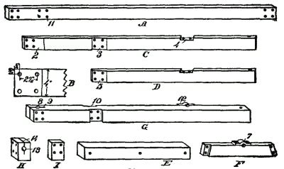
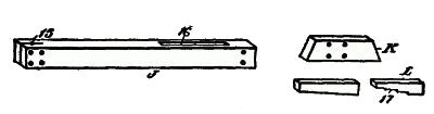
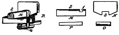
WOOD TURNINGAdvantages of Wood Turning.—This is not, strictly, in the carpenter's domain; but a knowledge of its use will be of great service in the trade, and particularly in cabinet making. I urge the ingenious youth to rig up a wood-turning lathe, for the reason that it is a tool easily made and one which may be readily turned by foot, if other power is not available. Simple Turning Lathe.—A very simple turning lathe may be made by following these instructions: The Rails.—Procure two straight 2" × 4" scantling (A), four feet long, and planed on all sides. Bore four ⅜-inch holes at each end, as shown, and 10 inches from one end four more holes. A plan of these holes is shown in B, where the exact spacing is indicated. Then prepare two pieces 2" × 4" scantling (C), planed, 42 inches long, one end of each being chamfered off, as at 2, and provided with four bolt holes. Ten inches down, and on the same side, with the chamfer (2) is a cross gain (3), the same angle as the chamfer. Midway between the cross gain (3) and the lower end of the leg is [Pg 139] a gain (4) in the edge, at right angles to the cross gain (3). The Legs.—Now prepare two legs (D) for the tail end of the frame, each 32 inches long, with a chamfer (5) at one end, and provided with four bolt holes. At the lower end bore a bolt hole for the cross base piece. This piece (E) is 4" × 4", 21 inches long, and has a bolt hole at each end and one near the middle. The next piece (F) is 2" × 4", 14½ inches long, provided with a rebate (6) at each end, to fit the cross gains (4) of the legs (C). Near the middle is a journal block (7). Centering Blocks.—Next provide a 4" × 4" piece (G), 40 inches long, through which bore a ¾-inch hole (8), 2 inches from the upper end, and [Pg 140] four bolt holes at right angles to the shaft hole (8). Then, with a saw split down this bearing, as shown at 9, to a point 4 inches from the end. Ten inches below the upper end prepare two cross gains (10), each an inch deep and four inches wide. In these gains are placed the top rails (A), so the bolt holes in the gains (10) will coincide with the bolt holes (11) in the piece A. Below the gains (10) this post has a journal block (12), intended to be in line with the journal block (7) of the piece F. Then make a block (H) 2" × 4", and 6 inches long. This also must have a shaft hole (B), and a saw kerf (14), similar to the arrangement on the upper end of the post (G); also bore four bolt holes, as shown. This block rests between the upper ends of the lugs (C). Another block (I), 2" × 4", and 6 feet long, with four bolt holes, will be required for the tail end of the frame, to keep the rails (A) two inches apart at that end. The Tail Stock.—This part of the structure is made of the following described material: [Pg 141] Procure a scantling (J), planed, 4" × 4", 24 inches long, the upper end of which is to be provided with four bolt holes, and a centering hole (15). At the lower end of the piece is a slot (16) 8 inches long and 1½ inches wide, and there are also two bolt holes bored transversely through the piece to receive bolts for reinforcing the end. A pair of cheekpieces (K), 2" × 4", and each 12 inches long, are mitered at the ends, and each has four bolt holes by means of which the ends may be bolted to the upright (J). Then a step wedge (L) is made of 1⅜" × 2" material, 10 inches long. This has at least four steps (17), each step being 2 inches long. A wedge 1⅜ inches thick, 10 inches long, and tapering from 2 inches to 1⅜ inches, completes the tail-stock. The Tool Rest.—This is the most difficult part of the whole lathe, as it must be rigid, and so constructed that it has a revolvable motion as well as being capable of a movement to and from the material in the lathe. Select a good 4" × 4" scantling (M), 14 inches long, as shown in Fig. 243. Two inches from one end cut a cross gain (I), 1½ inches deep and 1 inch wide, and round off the upper edge, as at 2. Then prepare a piece (N), 1 inch thick, 8 inches wide, and 10 inches long. Round off the upper edge to form a nose, and midway between its ends [Pg 142] cut a cross gain 4 inches wide and 1½ inches deep. The lower margin may be cut away, at an angle on each side of the gain. All that is necessary now is to make a block (O), 8 inches long, rounded on one edge, and a wedge (P). A leather belt or strap (Q), 1½ inches wide, formed into a loop, as shown in the perspective view (R), serves as a means for holding the rest rigidly when the wedge is driven in. The Tool Rest.—This is the most difficult part of the whole lathe, as it must be rigid, and so constructed that it has a revolvable motion as well as being capable of a movement to and from the material in the lathe. Materials.—Then procure the following bolts:
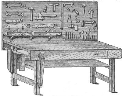
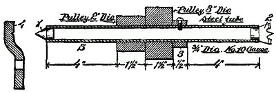
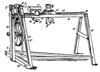
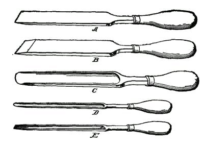
The Mandrel.—A piece of steel tubing (S), No. 10 gage, ¾ inch in diameter, 11½ inches long, will be required for the mandrel. Get a blacksmith, if a machine shop is not convenient, to put a fixed center (1) in one end, and a removable centering member (2) in the other end. On this mandrel place a collar (3), held by a set screw, and alongside of it a pair of pulleys, each 1½ inches wide, one of them, being, say, 2 inches in diameter, and the other 3 inches. This mandrel is held in position by means of the posts of the frame which carry the split journal bearings. This form of bearing will make a durable lathe, free from chattering, as the bolts can be used for tightening the mandrel whenever they wear. The center point (1) is designed to rest against a metal plate (4) bolted to the wooden post, as shown in the large drawing. Fly-wheel.—It now remains only to provide a fly-wheel and treadle with the communicating belt. The fly-wheel may be of any convenient size, or it may be some discarded pulley or wheel. Suppose it is two feet in diameter; then, as your small pulley is 2 inches in diameter, each revolution of the large wheel makes twelve revolutions in the mandrel, and you can readily turn the wheel eighty [Pg 144] times a minute. In that case your mandrel will revolve 960 revolutions per minute, which is ample speed for your purposes. The wheel should be mounted on a piece of ¾-inch steel tubing, one end having a crank 3 inches long. This crank is connected up by a pitman rod, with the triangularly shaped treadle frame. Such a lathe is easily made, as it requires but little metal or machine work, and it is here described because it will be a pleasure for a boy to make such a useful tool. What he needs is the proper plan and the right dimensions to carry out the work, and his own ingenuity will make the modifications suitable to his purpose. The illustration (Fig. 245) shows such a lathe assembled ready for work. The Tools Required.—A few simple tools will complete an outfit capable of doing a great variety of work. The illustration (Fig. 246) shows five chisels, of which all other chisels are modifications. A and B are both oblique firmer chisels, A being ground with a bevel on one side only, and B with a bevel on each side. C is a broad gage, with a hollow blade, and a curved cutting edge, ground with a taper on the rounded side only. D is a narrow gage similarly ground, and E is a V-shaped gage. It may be observed that in wood-turning sharp tools are absolutely necessary, hence a good oil stone, or several small, round and V-shaped stones should be used. Chapter 15, On the Use of Stains For more detailed infomation on wood turning see "A Course In Wood Turning" by Archie S. Milton & Otto K. Wohlers at Sawdust Making 101 |