![]()
Reprint from THE "HOW-TO-DO-IT" BOOKSCARPENTRY FOR BOYS
|
I - II - III - IV - V - VI - VII - VIII - IX - X - XI - XII - XIII - XIV - XV - XVI - XVII - XVIII - XIX - XX - XXI
CHAPTER XVIII
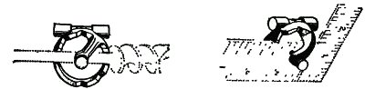
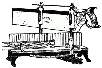
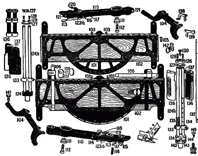
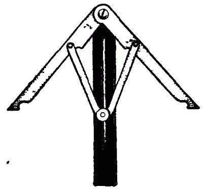
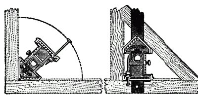
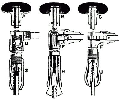
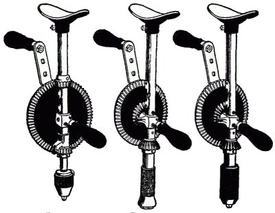
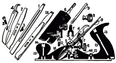
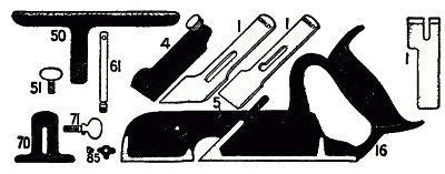
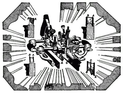
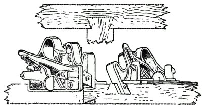
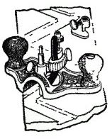
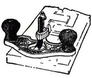
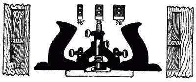
SPECIAL TOOLS AND THEIR USESIn the foregoing chapters we have referred the reader to the simple tools, but it is thought desirable to add to the information thus given, an outline of numerous special tools which have been devised and are now on the market. Bit and Level Adjuster.—It is frequently necessary to bore holes at certain angles. This can be done by using a bevel square, and holding it so one limb will show the boring angle. But this is difficult to do in many cases. This tool has three pairs of V slots on its back edges. The shank of the bit will lie in these slots, as shown in Fig. 266, either vertically, or at an angle of 45 degrees, and boring can be done with the utmost accuracy. It may be attached to a Carpenter's square, thus making it an accurate plumb or level. Miter Boxes.—The advantages of metal miter boxes is apparent, when accurate work is required. The illustration, Fig. 267, shows a metal tool of this kind, in which the entire frame is in one solid casting. The saw guide uprights are clamped in tapered sockets in the swivel arm and can be adjusted to hold the saw without play, and this will also counteract a saw that runs out of true, due to improper setting or filing. A second socket in the swivel arm permits the use of a short saw or allows a much longer stroke with a standard or regular saw. The swivel arm is provided with a tapering index pin which engages in holes placed on the under side of the base. The edge of the base is graduated in degrees, as plainly shown, and the swivel arm can be set and automatically fastened at any degree desired. The uprights, front and back are graduated in sixteenths of inches, and movable stops can be set, by means of thumb-screw to the depth of the cut desired. Figure 268 shows the parts of the miter box, in which the numbers designate the various parts: 101 is the frame; 102 the frame board; 104 frame leg; 106 guide stock; 107 stock guide clamp; 109 stock guide plate; 110 swivel arm; 111 swivel arm bushing; 112 swivel bushing screw; 113 index clamping lever; 115 index clamping lever catch; 116 index clamping lever spring; 122 swivel complete; 123 T-base; 124½ uprights; 126 saw guide cap; 127 saw guide cap plate; 132 saw guide tie bar; 133 left saw guide stop and screw; 134 right side guide stop and screw; 135 saw guide stop spring; 136 saw guide cylinder; 137 saw guide cylinder plate; 138 trip lever (back); 139 trip lever (front); 141 leveling screw; 142 trip clamp and screw; 146 T-base clamp screw. Angle Dividers.—This is another tool, which does not cost much and is of great service to the carpenter in fitting moldings where they are applied at odd angles. To lay out the cut with an ordinary bevel necessitates the use of dividers and a second handling of the bevel, making three operations. The "Odd Job" Tool.—A most useful special tool, which combines in its make-up a level, plumb try-square, miter-square, bevel, scratch awl, depth gage, marking gage, miter gage, beam compass, and a one-foot rule. To the boy who wishes to economize in the purchase of tools this is an article which should be obtained. Figure 270 shows the simplicity of the tool, and how it is applied in use. Bit Braces.—These tools are now made with so many improved features that there is really no excuse for getting poor tools. The illustrations show merely the heads and the lower operating parts of the tools. Fig. 271 shows a metal-clad ball-bearing head, so called, as its under side is completely encased in metal securely screwed to the wood and revolving against the ball thrust bearing. D represents a concealed ratchet in which the cam ring governs the ratchet, and, being in line with the bit, makes it more convenient in handling than when it is at right angles. The ratchet parts are entirely enclosed, thus keeping out moisture and dirt, retaining lubrication and protecting the users' hands. The ratchet mechanism is interchangeable, and may be taken apart by removing one screw. The two-piece clutch, which is drop forged, is backed by a very strong spring, insuring a secure lock. When locked, ten teeth are in engagement, while five are employed while working at a ratchet. It has universal jaws (G) for both wood and metal workers. In Fig. 272, B represents a regular ball bearing head, with the wood screw on the large spindle and three small screws to prevent its working loose. This also has a ball thrust. E is the ratchet box, and this shows the gear teeth cut on the extra heavy spindle, and encased, so that the user's hands are protected from the teeth. The interlocking jaws (H), which are best for taper shanks, hold up to No. 2 Clark's expansion, and are therefore particularly adapted for carpenter's use. In Fig. 273 the plain bearing head (C) has no ball thrust. The head is screwed on the spindle and held from turning off by two small screws. The open ratchet (F) shows the gear pinned to the spindle and exposed. This has alligator jaws (J), and will hold all ordinary size taper shank bits, also small and medium round shank bits or drills. Steel Frame Breast Drill.—These drills are made with both single and double speed, each speed having three varieties of jaws. The single speed is very high, the ratio being 4½ to 1, which makes it desirable to use for small drills, or for use in wood. A level is firmly set in the frames of these tools to assist the user to maintain a horizontal position in boring. Each of the forms shown has a ball thrust bearing between the pinion and frame. The breast plate may be adjusted to suit and is locked by a set screw. The spindle is kept from turning while changing drills, by means of the latch mounted on the frame, and readily engaging with the pinion. The crank is pierced in three places so that the handle can be set for three different sweeps, depending on the character of the work. Figure 274 has a three jaw chuck, and has only single speed. Figure 275 has an interlocking jaw, and is provided with double speed gearing. Figure 276 has a universal jaw, and double speed. Planes.—The most serviceable planes are made in iron, and it might be well to show a few of the most important, to bring out the manner employed to make the adjustments of the bits. In order to familiarize the boy with the different terms used in a plane, examine Figure 277. The parts are designated as follows: 1A is the double plane iron; 1 single plane iron; 2 plane iron cap; 3 cap screw; 4 lever cap; 5 lever cap screw; 6 frog complete; 7 Y adjusting lever; 8 adjusting nut; 9 lateral adjusting lever; 11 plane handle; 12 plane knob; 13 handle bolt and nut; 14 knob bolt and nut; 15 plane handle screw; 16 plane bottom; 44 frog pin; 45 frog clamping screw; 46 frog adjusting screw. Rabbeting, Matching and Dado Planes.—Figure 278 shows a useful form of plane for the reason that it is designed to receive a variety of irons, adapted to cut rabbets. The detached sections of Fig. 278 show the various parts, as well as the bits which belong to it. 1, 1 represent the single plane irons; 4 the lever cap; 16 the plane bottom, 50 the fence; 51 the fence thumb screw; 61 the short arm; 70 the adjustable depth gage; 71 the depth gage which goes through the screw; and 85 the spurs with screws. Molding and Beading Plane.—A plane of the character shown in Fig. 279 will do an immense variety of work in molding, beading and dado work, and is equally well adapted for rabbeting, for filletsters and for match planing. The regular equipment with this tool comprises fifty-two cutters. As shown in Fig. 279, the plane has a main stock (A), which carries the cutter adjustment, a handle, a depth gage, a slitting gage, and a steel bottom forming a bearing for the other end of the cutter, and slides on arms secured to the main stock. This bottom can be raised or lowered, so that, in addition to allowing the use of cutters of different widths, cutters can be used having one edge higher or lower than the edge supported in the main stock. The auxiliary center bottom (C), which can be adjusted for width or depth, fulfils the requirement of preventing the plane from tilting and gouging the work. The fence D has a lateral adjustment by means of a screw, for extra fine work. The four small cuts in the corners show how the bottoms should be set for different forms of cutters, and the great importance of having the fences adjusted so that the cutters will not run. The samples of work illustrated show some of the moldings which can be turned out with the plane. Dovetail Tongue and Groove Plane.—This is a very novel tool, and has many features to recommend it. Figure 280 shows its form, and how it is used. It is designed to make the dovetailed tongue as well as the groove. It will cut any size groove and tongues to fit with sides of twenty degrees flare, where the width of the neck is more than one-quarter of an inch thick, and the depth of the groove not more than three-quarters of an inch. The tongue and groove are cut separately, and can be made with parallel or tapering sides. The operation of the plane is very simple. Router Planes.—This is a type of plane used for surfacing the bottom of grooves or other depressions parallel with the general surface of the work. The planes are made in two types, one, like Fig. 281, which has a closed throat, and the other, Fig. 282, with an open throat. Both are serviceable, but the latter is preferable. These planes will level off bottoms of depression, very accurately, and the tool is not an expensive one. Door Trim Plane.—This is a tool for making mortises for butts, face plates, strike plates, escutcheons, and the like, up to a depth of 5/16, and a width of 3 inches. The principal feature in the plane is the method of mounting the cutter, which can be instantly set to work from either end of the plane or across it. The cutter, as shown in Fig. 283, is cushioned by a spring which prevents taking a heavier chip than can be easily carried. A fence regulates the position of the cut and insures the sides of the cut being parallel. The depth of the cut is governed by a positive stop. By removing the fence and locking the cutter post with the thumb screw, instead of using the spring, a very superior router plane is obtained. |