![]()
Reprint from THE "HOW-TO-DO-IT" BOOKSCARPENTRY FOR BOYS
|
I - II - III - IV - V - VI - VII - VIII - IX - X - XI - XII - XIII - XIV - XV - XVI - XVII - XVIII - XIX - XX - XXI
CHAPTER XI
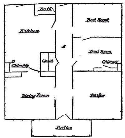
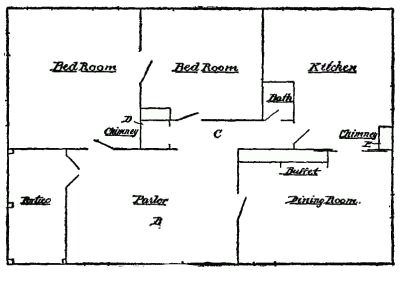
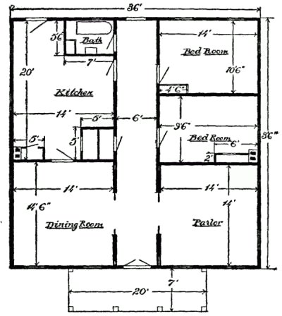
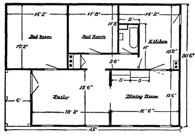
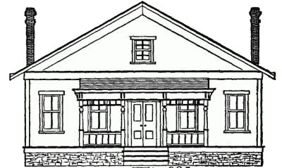
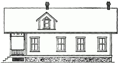
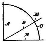
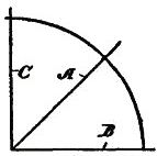
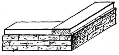
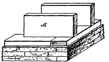
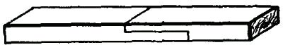
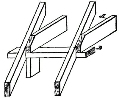
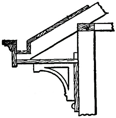
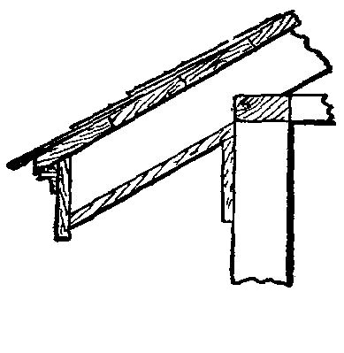
HOUSE BUILDINGHouse building is the carpenter's craft; cabinet-making the joiner's trade, yet both are so intimately associated, that it is difficult to draw a line. The same tools, the same methods and the same materials are employed. There is no trade more ennobling than home building. It is a vocation which touches every man and woman, and to make it really an art is, or should be, the true aspiration of every craftsman. The House and Embellishments.—The refined arts, such as sculpture and painting, merely embellish the home or the castle, so that when we build the structure it should be made with an eye not only to comfort and convenience, but fitting in an artistic and æsthetic sense. It is just as easy to build a beautiful home as an ugly, ungainly, illy proportioned structure. Beauty Not Ornamentation.—The boy, in his early training, should learn this fundamental truth, that beauty, architecturally, does not depend upon ornamentation. Some of the most beautiful structures in the world are very plain. Beauty consists in proportions, in proper correlation of parts, and in adaptation for the uses to which the structure is to be put. Plain Structures.—A house with a plain façade, having a roof properly pitched and with a simple cornice, if joined to a wing which is not ungainly or out of proper proportions, is infinitely more beautiful than a rambling structure, in which one part suggests one order of architecture and the other part some other type or no type at all, and in which the embellishments are out of keeping with the size or pretensions of the house. Colonial Type.—For real beauty, on a larger scale, there is nothing to-day which equals the old Colonial type with the Corinthian columns and entablature. The Lee mansion, now the National Cemetery, at Washington, is a fine example. Such houses are usually square or rectangular in plan, severely plain, with the whole ornamentation consisting of the columns and the portico. This type presents an appearance of massiveness and grandeur and is an excellent illustration of a form wherein the main characteristic of the structure is concentrated or massed at one point. The Church of the Madelaine, Paris, is another striking example of this period of architecture. Of course, it would be out of place with cottages and small houses, but it is well to study and to know what forms are most available and desirable to adopt, and particularly to know something of the art in which you are interested. The Roof the Keynote.—Now, there is one thing which should, and does, distinguish the residence from other types of buildings, excepting churches. It is the roof. A house is dominated by its covering. I refer to the modern home. It is not true with the Colonial or the Grecian types. In those the façade or the columns and cornices predominate over everything else. Bungalow Types.—If you will take up any book on bungalow work and note the outlines of the views you will see that the roof forms the main element or theme. In fact, in most buildings of this kind everything is submerged but the roof and roof details. They are made exceedingly flat, with different pitches with dormers and gables intermingled and indiscriminately placed, with cornices illy assorted and of different kinds, so that the multiplicity of diversified details gives an appearance of great elaboration. Many of those designs are monstrosities and should, if possible, be legally prohibited. I cannot attempt to give even so much as an outline of what constitutes art in its relation to building, but my object is to call attention to this phase of the question, and as you proceed in your studies and your work you will realize the value and truthfulness of the foregoing observations. General House Building.—We are to treat, generally, on the subject of house building, how the work is laid out, and how built, and in doing so I shall take a concrete example of the work. This can be made more effectual for the purpose if it is on simple lines. Building Plans.—We must first have a plan; and the real carpenter must have the ability to plan as well as to do the work. We want a five-room house, comprising a parlor, dining room, two bedrooms, a kitchen and a bathroom. Just a modest little home, to which we can devote our spare hours, and which will be neat and comfortable when finished. It must be a one-story house, and that fact at once settles the roof question. We can make the house perfectly square in plan, or rectangular, and divide up the space into the proper divisions. The Plain Square Floor Plan will first be taken up, as it is such an easy roof to build. Of course, it is severely plain. Fig. 221 shows our proposed plan, drawn in the rough, without any attempts to measure the different apartments, and with the floor plan exactly square. Supposing we run a hall (A) through the middle. On one side of this let us plan for a dining room and a kitchen, a portion of the kitchen space to be given over to a closet and a bathroom. The chimney (B) must be made accessible from both rooms. On the other side of the hallway the space is divided into a parlor and two bedrooms. The Rectangular Plan.—In the rectangular floor plan (Fig. 222) a portion of the floor space is cut out for a porch (A), so that we may use the end or the side for the entrance. Supposing we use the end of the house for this purpose. The entrance room (B) may be a bedroom, or a reception and living room, and to the rear of this room is the dining room, connected with the reception room by a hall (C). This hall also leads to the kitchen and to the bathroom, as well as to the other bedroom. The parlor is connected with the entrance room (B), and also with the bedroom. All of this is optional, of course. There are also two chimneys, one chimney (D) having two flues and the other chimney (E) having three flues, so that every room is accommodated. Room Measurements.—We must now determine the dimensions of each room, and then how we shall build the roof. In Figs. 223 and 224, we have now drawn out in detail the sizes, the locations of the door and windows, the chimneys and the closets, as well as the bathroom. All this work may be changed or modified to suit conditions and the taste of the designer. Front and Side Lines.—From the floor diagram, and the door and window spaces, as marked out, we may now proceed to lay out rough front and side outlines of the building. The ceilings are to be 9 feet, and if we put a rather low-pitched roof on the square structure (Fig. 223) the front may look something like Fig. 225, and a greater pitch given to the rectangular plan (Fig. 224) will present a view as shown in Fig. 226. The Roof.—The pitch of the roof (Fig. 225) is what is called "third pitch," and the roof (Fig. 226) has a half pitch. A "third" pitch is determined as follows: Roof Pitch.—In Fig. 227 draw a vertical line (A) and join it by a horizontal line (B). Then strike a circle (C) and step it off into three parts. The line (D), which intersects the first mark (E) and the angle of the lines (A, B), is the pitch. In Fig. 228 the line A is struck at 15 degrees, which is halfway between lines B and C, and it is, therefore, termed "half-pitch." Thus, we have made the ground plans, the elevations and the roofs as simple as possible. Let us proceed next with the details of the building. The Foundation.—This may be of brick, stone or concrete, and its dimensions should be at least 1½ inches further out than the sill. The Sills.—We are going to build what is called a "balloon frame"; and, first, we put down the sills, which will be a course of 2" × 6", or 2" × 8" joists, as in Fig. 229. The Flooring Joist.—The flooring joists (A) are then put down (Fig. 230). These should extend clear across the house from side to side, if possible, or, if the plan is too wide, they should be lapped at the middle wall and spiked together. The ends should extend out flush with the outer margins of the sills, as shown, but in putting down the first and last sill, space must be left along the sides of the joist of sufficient width to place the studding. The Studding.—The next step is to put the studding into position. 4" × 4" must be used for corners and at the sides of door and window openings. [Pg 124] 4" × 6" may be used at corners, if preferred. Consult your plan and see where the openings are for doors and windows. Measure the widths of the door and window frames, and make a measuring stick for this purpose. You must leave at least one-half inch clearance for the window or door frame, so as to give sufficient room to plumb and set the frame. Setting Up.—First set up the corner posts, plumbing and bracing them. Cut a top plate for each side you are working on. The Plate.—As it will be necessary in our job to use two or more lengths of 2" × 4" scantling for the plate, it will be necessary to join them together. Do this with a lap-and-butt joint (Fig. 231). Then set up the 4" × 4" posts for the sides of the doors and windows, and for the partition walls. The plate should be laid down on the sill, and marked with a pencil for every scantling to correspond with the sill markings. The plate is then put on and spiked to the 4" × 4" posts. Intermediate Studding.—It will then be an [Pg 125] easy matter to put in the intermediate 2" × 4" studding, placing them as nearly as possible 16 inches apart to accommodate the 48-inch plastering lath. Wall Headers.—When all the studding are in you will need headers above and rails below the windows and headers above all the doors, so that you will have timbers to nail the siding to, as well as for the lathing. Ceiling Joists.—We are now ready for the ceiling joists, which are, usually, 2" × 6", unless there is an upper floor. These are laid 16 inches apart from center to center, preferably parallel with the floor joist. It should be borne in mind that the ceiling joist must always be put on with reference to the roof. Thus, in Fig. 232, the ceiling joists (A) have their ends resting on the plate (B), so that the rafters are in line with the joists. Braces.—It would also be well, in putting up the studding, to use plenty of braces, although for a one-story building this is not so essential as in two-story structures, because the weather boarding serves as a system of bracing. The Rafters.—These may be made to provide for the gutter or not, as may be desired. They should be of 2" × 4" scantling. The Gutter.—In Fig. 233 I show a most serviceable way to provide for the gutter. A V-shaped notch is cut out of the upper side of the rafter, in which is placed the floor and a side. This [Pg 127] floor piece is raised at one end to provide an incline for the water. A face-board is then applied and nailed to the ends of the rafters. This face-board is surmounted by a cap, which has an overhang, beneath which is a molding of any convenient pattern. The face-board projects down at least two inches below the angled cut of the rafter, so that when the base-board is applied, the lower margin of the face-board will project one inch below the base. This base-board is horizontal, as you will see. The facia-board may be of any desired width, and a corner molding should be added. It is optional to use the brackets, but if added they should be spaced apart a distance not greater than twice the height of the bracket. A much simpler form of gutter is shown in Fig. 234, in which a V-shaped notch is also cut in the rafter, and the channel is made by the pieces. The end of the rafter is cut at right angles, so the face-board is at an angle. This is also surmounted by an overhanging cap and a molding. The base is nailed to the lower edges of the rafters, and the facia is then applied. In Fig. 234a the roof has no gutter, so that the end of the rafter is cut off at an angle and a molding applied on the face-board. The base is nailed to the rafters. This is the cheapest and simplest form of structure for the roof. Setting Door and Window Frames.—The next step in order is to set the door and window frames preparatory to applying the weather boarding. It is then ready for the roof, which should be put on before the floor is laid. Plastering and Inside Finish.—Next in order is the plastering, then the base-boards and the casing; and, finally, the door and windows should be fitted into position. Enough has been said here merely to give a general outline, with some details, how to proceed with the work. Chapter 12, Bridges, Trussed Work and Like Structures Back to Table of Contents |