CHAPTER VIIIofPRACTICAL MECHANICS FOR BOYS
|
The ability to read drawings is a necessary part of the boy's education. To know how to use the tools, is still more important. In conveying an idea about a piece of mechanism, a sketch is given. Now, the sketch may be readable in itself, requiring no explanation, or it may be of such a nature that it will necessitate some written description.
Lines in Drawing.—- In drawing, lines have a definite meaning. A plain circular line, like Fig. 95, when drawn in that way, conveys three meanings: It may represent a rim, or a bent piece of wire; it may illustrate a disk; or, it may convey the idea of a ball.
Suppose we develop them to express the three forms accurately. Fig. 96, by merely adding an interior line, shows that it is a rim. There can be no further doubt about that expression.
Fig. 97 shows a single line, but it will now be noticed that the line is thickened at the lower right-hand side, and from this you can readily infer that it is a disk.
Shading.—Fig. 98, by having a few shaded lines on the right and lower side, makes it have the appearance of a globe or a convex surface.
Shading or thickening the lines also gives another expression to the same circular line.
In Fig. 99, if the upper and left-hand side of the circle is heavily shaded, it shows that the area within the circle is depressed, instead of being raised.
Direction of Shade.—On the other hand, if the shading lines, as in Fig. 100, are at the upper left-hand side, then the mind at once grasps the idea of a concave surface.
The first thing, therefore, to keep in mind, is this fact: That in all mechanical drawing, the light is supposed to shine down from the upper left-hand corner and that, as a result, the lower vertical line, as well as the extreme right-hand vertical line, casts the shadows, and should, therefore, be made heavier than the upper horizontal, and the left-hand vertical lines.
There are exceptions to this rule, which will be readily understood by following out the illustrations in the order given below.
Perspectives.—The utility of the heavy lines will be more apparent when drawing square, rectangular, or triangular objects.
Let us take Fig. 101, which appears to be the perspective of a cube. Notice that all lines are of the same thickness. When the sketch was first brought to me I thought it was a cube; but the explanation which followed, showed that the man who made the sketch had an entirely different meaning.
He had intended to convey to my mind the idea of three pieces, A, B, C, of metal, of equal size, joined together so as to form a triangularly shaped pocket as shown in Fig. 101. The addition of the inner lines, like D, quickly dispelled the suggestion of the cube.
"But," he remarked, "I want to use the thinnest metal, like sheets of tin; and you show them thick by adding the inner lines."
Such being the case, if we did not want to show thickness as its structural form, we had to do it by making the lines themselves and the shading give that structural idea. This was done by using the single lines, as in Fig. 103, and by a slight shading of the pieces A, B, C.
The Most Pronounced Lines.—If it had been a cube, or a solid block, the corners nearest the eye would have been most pronounced, as in Fig. 104, and the side next to the observer would have been darkest.
This question of light and shadow is what expresses the surface formation of every drawing. Simple strokes form outlines of the object, but their thickness, and the shading, show the character enclosed by the lines. Direction of Light.—Now, as stated, the casting of the shadow downward from the upper left-hand corner makes the last line over which it passes the thickest, and in Figs. 105 and 106 they are not the extreme lines at the bottom and at the right side, because of the close parallel lines.
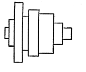
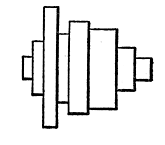
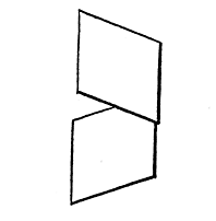
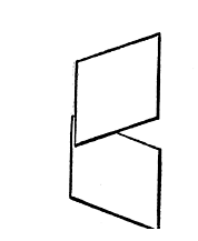
In Figs. 109 and 110 the blades superposed on the other are very thin, and the result is the lines at the right side and bottom are made much heavier.
 |
 |
| Fig. 107. | Fig. 108. |
| Illustrating Heavy Lines | |
This is more fully shown in Figs. 107 and 108. Notice the marked difference between the two figures, both of which show the same set of pulleys, and the last figure, by merely having the lower and the right-hand lines of each pulley heavy, changes the character of the representation, and tells much more clearly what the draughtsman sought to convey.
Scale Drawings.—All drawings are made to a scale where the article is large and cannot be indicated the exact size, using parts of an inch to represent inches; and parts of a foot to represent feet.
In order to reduce a drawing where a foot is the unit, it is always best to use one-and-a-half inches, or twelve-eighths of an inch, as the basis. In this way each eighth of an inch represents an inch. If the drawing should be made larger, then use three inches, and in that way each inch would be one-quarter of an inch.
 |
 |
| Fig. 109. | Fig. 110. |
| Illustrating Heavy Lines | |
The drawing should then have marked, in some conspicuous place, the scale, like the following: "Scale, 1 1/2" = 1'"; or, "Scale 3" = 1'."
Degree, and What it Means.—A degree is not a measurement. The word is used to designate an interval, a position, or an angle. Every circle has 360 degrees, and when a certain degree is mentioned, it means a certain angle from what is called a base line.
Look at Fig. 111. This has a vertical line A, and a horizontal line B. The circle is thus divided into four parts, and where these lines A, B, cross the circle are the cardinal points. Each of the four parts is called a quadrant, and each quadrant has 90 degrees.
Any line, like C, which is halfway between A and B, is 45 degrees. Halfway between A and C, or between B and C, like the line D, is 22 1/2 degrees.
Memorizing Angles.—It is well to try and remember these lines by fixing the angles in the memory. A good plan is to divide any of the quadrants into thirds, as shown by the points E, F, and then remember that E is 30 degrees from the horizontal line B, and that F is 60 degrees. Or, you might say that F is 30 degrees from the vertical line A, and E 60 degrees from A. Either would be correct.
Section Lining.—In representing many parts of a machine, or article, it is necessary to show the parts cut off, which must be illustrated by what is called "section lining." Adjacent parts should have the section lines running at right angles to each other, and always at 45 degrees.
Look at the outside and then the inside views of Fig. 112, and you will see how the contiguous parts have the angles at right angles, and clearly illustrate how every part of the wrench is made. Skill in depicting an article, for the purpose of constructing it from the drawing, will make the actual work on the bench and lathe an easy one.
Making Ellipses and Irregular Curves.—This is the hardest thing to do with drawing tools. A properly constructed elliptical figure is difficult, principally, because two different sized curves are required, and the pen runs from one curve into the other. If the two curves meet at the wrong place, you may be sure you will have a distorted ellipse.
Follow the directions given in connection with Fig. 113, and it will give you a good idea of merging the two lines.
First. Draw a horizontal line, A, which is in the direction of the major axis of the ellipse—that is, the longest distance across. The narrow part of the ellipse is called the minor axis.
Second. Draw a perpendicular line, B, which we will call the center of the ellipse, where it crosses the line A. This point must not be confounded with the focus. In a circle the focus is the exact center of the ring, but there is no such thing in an ellipse. Instead, there are two focal points, called the foci, as you will see presently.
Third. Step off two points or marking places, as we shall term them, equidistant from the line B, and marked C, C. These marks will then represent the diameter of the ellipse across its major axis.
Fourth. We must now get the diameter of the minor axis, along the line B. This distance will depend on the perspective you have of the figure. If you look at a disk at an angle of about 30 degrees it will be half of the distance across the major axis
So you may understand this examine Fig. 114. The first sketch shows the eye looking directly at the disk 1. In the second sketch the disk is at 30 degrees, and now the lines 2 2, from the eye, indicate that it is just half the width that it was when the lines 3 3 were projected. The marks D D, therefore, indicate the distance across the minor axis in Fig. 113.
Fifth. We must now find the focal points of the ellipse. If the line A on each side of the cross line B is divided into four parts, the outer marks E may be used for the foci, and will be the places where the point of the compass, or bow pen, is to be placed.
Sixth. Describe a circle F, so it passes through the mark C, and move the point of the compass to the center of the ellipse, at the star, and describe a circle line G, from the mark C to the line B. This will give a centering point H. Then draw a line I from H to E, and extend it through the circle F.
Seventh. If the point of the compass is now put at H, and the pencil or pen on the circle line F, the curve J can be drawn, so the latter curve and the curve F will thus merge perfectly at the line I.
The Focal Points.—The focal points can be selected at any arbitrary point, between C and the line B, and the point H may be moved closer to or farther away from the line A, and you will succeed in making the ellipse correct, if you observe one thing, namely: The line I, which must always run from H to E, and intersects the circle F, is the starting or the ending point for the small curve F or the large circle J.
Isometric and Perspective.—A figure may be drawn so as to show an isometric or a perspective view. Thus, a cube can be drawn so as to make an isometric figure, as in Fig. 115, where the three sides are equal to each other.
Isometric means a method of drawing any object in such a manner that the height, length and breadth may be shown in the proportion they really bear to each other. Fig. 115 has the sides not only equal to each other, in appearance to the eye, but they have the same outlines and angles.
Contrast this figure with Figs. 116 and 117. In Fig. 116 two of the sides are equal in angles and outline; and in Fig. 117 each side has a different outline, and different angles. Nevertheless, all the cubes are, in reality, of the same dimension.
The Protractor.—This is a most useful tool for the draughtsman. It enables the user to readily find any angle. Fig. 118 shows an approved form of the tool for this purpose.
Suggestions in Drawing.—As in the use of all other tools, so with the drawing instrument, it must be kept in proper order. If the points are too fine they will cut the paper; if too blunt the lines will be ragged. In whetting the points hold the pen at an angle of 12 degrees. Don't make too long an angle or slope, and every time you sharpen hold it at the same angle, so that it is ground back, and not at the point only.
Holding the Pen.—The drawing pen should be held as nearly vertical as possible. Use the cleaning rag frequently. If the ink does not flow freely, after you have made a few strokes, as is frequently the case, gently press together the points. The least grit between the tines will cause an irregular flow
Inks.—As prepared liquid inks are now universally used, a few suggestions might be well concerning them. After half the bottle has been used, add a half teaspoonful of water, shake it well, and then strain it through a fine cotton cloth. This will remove all grit and lint that is sure to get into the bottle however carefully it may be corked.
Tracing Cloth.—It is preferable to use the dull side of the tracing cloth for the reasons that, as the cloth is rolled with the glossy side inside, the figure when drawn on the other side will be uppermost, and will thus lie flat; and on the other hand, the ink will take better on the dull side.
If the ink does not flow freely, use chalk, fine pumice stone, or talc, and rub it in well with a clean cloth, and then wipe off well before beginning to trace
Detail Paper.—The detail paper, on which the drawing is first made in pencil, should show the figure accurately, particularly the points where the bow pen are to be used, as well as the measurement points for the straight lines.
How to Proceed.—Make the circles, curves, and irregular lines first, and then follow with the straight lines. Where the point of the circle pen must be used for a large number of lines, as, for instance, in shading, the smallest circles should be made first, and the largest circles last, because at every turn the centering hole becomes larger, and there is liability to make the circles more or less irregular. Such irregularity will not be so noticeable in the large curves as in the smaller ones.
Indicating Material by the Section Lines.—In section lining different materials can be indicated by the character of the lines, shown in Fig. 120.
To Chapter IX - Treatment and Use of Metals
To Table of Contents and Glossary