CHAPTER IVofPRACTICAL MECHANICS FOR BOYS
|
The most necessary tool in a machine shop is a file. It is one of the neglected tools, because the ordinary boy, or workman, sees nothing in it but a strip or a bar with a lot of cross grooves and edges, and he concludes that the only thing necessary is to rub it across a piece of metal until he has worn it down sufficiently for the purpose.
The First Test.—The fact is, the file is so familiar a tool, that it breeds contempt, like many other things closely associated in life.
Give the boy an irregular block of metal, and tell him to file it up square, and he will begin to realize that there is something in the handling of a file that never before occurred to him.
He will find three things to astonish him:
First: That of dimensions.
Second: The difficulty of getting it square.
Third: The character of the surface when he has finished it.
Filing an Irregular Block.—To file a block of an irregular character so that the dimensions are accurate, is a good test for an accomplished workman. The job is made doubly difficult if he is required to file it square at the same time. It will be found, invariably, that the sides will not be parallel, and by the time it is fully trued up the piece will be too small. See Figs. 44 and 45.
Then, unless the utmost care is taken, the flat sides will not be flat, but rounded.
Filing a Bar Straight.—The next test is to get the boy to file a bar straight. He has no shaper or planer for the purpose, so that it must be done by hand. He will find himself lacking in two things: The edge of the bar will not be straight; nor will it be square with the side of the bar.
 |
 |
| Fig. 44. Rounded Surface | Fig. 45. A Winding Face |
Filing Bar with Parallel Sides.—Follow up this test by requiring him to file up a bar, first, with two exactly parallel sides, and absolutely straight, so it will pass smoothly between the legs of a pair of calipers, and then file the two other sides in like manner.
Surfacing off Disks.—When the foregoing are completed there is still another requirement which, though it appears simple, is the supreme test. Set him to work at surfacing off a pair of disks or plates, say one and a half inches in diameter, so that when they are finished they will fit against each other perfectly flat.
A pair of such disks, if absolutely true, will hold together by the force of cohesion, even in a dry state, or they will, as it were, float against each other.
True Surfacing.—Prior to about 1850 the necessity of true surfacing was not so important or as well known as at the present time. About that period Sir J. Whitworth, an eminent English engineer and mechanic, called the attention of machinists to the great advantage arising from true surfaces and edges for all types of machinery, and he laid the foundation of the knowledge in accurating surfacing.
Precision Tools.—Due to his energy many precision tools were made, all tending to this end, and as a result machines became better and more efficient in every way.
It had this great advantage: It taught the workman of his day how to use the file and scraper, because both must be used conjunctively to make an absolutely flat plate.
Contrary to general beliefs, shapers and planers do not make absolutely accurate surfaces. The test of this is to put together two plates so planed off. There is just enough unevenness to permit air to get between the plates. If they were perfectly true they would exclude all air, and it would be a difficult matter to draw them apart.
Test of the Mechanic.—To make them perfectly flat, one plate has chalk rubbed over it, and the two plates are then rubbed together. This will quickly show where the high spots are, and the file and scraper are then used to cut away the metal.
In England the test of the mechanic used to be determined by his ability to file a piece of metal flat. It was regarded as the highest art. This is not the most desirable test at the present time, and it is recognized that a much severer test is to file a narrow piece exactly flat, and so that it will not have a trace of roundness, and be square from end to end.
Test Suggestions.—In a shop which does not have the advantage of a planer or shaper, there are so many articles which must be filed up, that it is interesting to know something of how the various articles are made with a file.
 |
 |
| Fig. 46. Hexagon Nut | Fig. 47. Hexagon Nut |
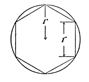
To file a hexagon, or six-sided nut will be a good test with a file. To do this a little study in geometrical lines will save a vast amount of time. In beginning the work, measure the radius with a divider, and then step off and make six marks equidistant from each other on the round surface.
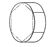
Use of the Dividers.—The distance between each of these points is equal to the radius, or half the diameter, of the round bar. See Fig. 46, which shows this. The marks should be scribed across the surface, as shown in Fig. 47, where the lines show the ends of the facets of the outside of the nut.
Do not let the file obliterate the lines at the rough cutting, but leave enough material so you can make a good finish at the line.
Cutting a Key-way.—Another job you may have frequent occasion to perform, is to cut a way for a key in a shaft and in a wheel hub. Naturally, this will be first roughed out with a cold chisel narrower than the key is to be, and also slightly shallower than the dimensions of the key.
A flat file should be used for the purpose, first a heavy rough one, for the first cutting. The better way is to have the key so it can be frequently tried while the filing process is going on, so that to fit the key in this way is a comparatively easy task.
Key-way Difficulties.—But the trouble commences when the groove is filed for the depth. Invariably, the mistake will be made of filing the width first, so the key will fit in. As a result, in deepening the groove the file will contact with the walls, and you have a key-way too wide for the key.
To avoid this, file the depth, or nearly so, and then with a fine file cut in the corners in the direction indicated by the dart, Fig. 48.
A proper key is square in cross section. In such a case the depth of the key-way, at each side wall, is just half the width of the key-way.
An excellent key-seat rule can be made by filing out two right-angled pieces, as shown in Fig. 49, which can be attached to the ordinary six-inch metal rule, and this will enable you to scribe the line accurately for the key-way on the shaft.
 |
 |
| Fig. 50. | Fig. 51. |
| Filing Metal Round | |
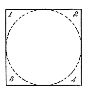
Filing Metal Round.—It is sometimes necessary to file a piece of metal round. This is a hard job, particularly where it is impossible to scribe the end of the piece. Suppose it is necessary to file up a bearing surface, or surfaces, intermediate the ends of a square bar.
You have in that case four sides to start from, the opposite sides being parallel with each other, so that you will have two dimensions, and four equal sides, as shown in Fig. 50.
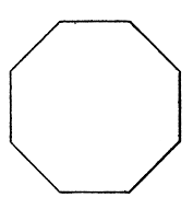
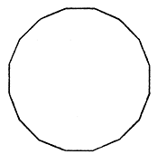
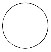
The first step will be to file off accurately the four corners 1, 2, 3, 4, so as to form eight equal sides or faces, as shown in Fig. 51. If you will now proceed to file down carefully the eight corners, so as to make sixteen sides, as in Fig. 52, the fourth set of corners filed down will make the filed part look like the illustration Fig. 53 with thirty-two faces.
 |
 |
| Fig. 52. | Fig. 53. |
| Making a Bar Round | |
This may be further filed down into sixty-four faces, and a few cuts of the finishing file will take off the little ridges which still remain. By using emery cloth, and wrapping it around the bearing portion, and changing it continually, while drawing it back and forth, will enable you to make a bearing which, by care, will caliper up in good shape.
Kinds of Files.—Each file has five distinct properties; namely: the length, the contour, the form in cross section, the kind of teeth, and the fineness of the teeth.
There are nine well-defined shapes for files. These may be enumerated as follows:
No. 1. The cotter file. The small kind is called a verge or pivot file.
No. 2. Square file, which may be tapering from end to end, or have parallel sides throughout.
No. 3. Watch pinion file. This may have its sides parallel or tapering, to make a knife-shaped file.
No. 4. Clock-pinion; which may be used for either nicking, piecing, or squaring-off purposes.
No. 5. Round, with parallel sides for gulleting purposes, or rat-tail when it tapers.
No. 6. Triangular, or three equally-sided body for saw filing.
No. 7. Equalizing file. This is parallel when used for making clock-pinions or endless screws; or for slitting, entering, warding, or making barrel holes, when the body of the file tapers.
No. 8. Cross, or double-round, half-file.
No. 9. Slitting file; which has parallel sides only. A cant file.
Character of the File Tooth.—Files are distinguished principally by the character of the oblique, or cross grooves and ridges which do the cutting and abrading when the file is drawn across the surface.
This is really more important than the shape, because the files, by their cuttings, are adapted for the various materials which they are to be used upon.
The files are classified as Double Cut, of which there are the rough, middle, bastard, second cut, smooth, and dead smooth.
The Float Cut, which is either rough, bastard or smooth; and
The Rasp Cut, either rough, bastard or smooth.
Several types are illustrated in Fig. 55, which show the characteristics of the various cuts.
The rasps are used principally for soft material, such as wood or for hoofs, in horse shoeing, hence they need not be considered in connection with machine-shop work.
Holding the File.—The common mistake on the part of the beginner is to drag the file across the work at an angle. The body of the file should move across straight and not obliquely.
Note this movement in Fig. 56 where the dash shows the correct movement of the file with relation to the work. Also observe that the file cutting ridges are not straight across the file, but at an angle to the direction of the dart.
Injuring Files.—Now the frequent practice is to use the file as shown in Fig. 57, in which case it is moved across obliquely. The result is that the angle of the file cut is so disposed that the teeth of the file do not properly aid in the cutting, but in a measure retard the operation.
File teeth are disposed at an angle for the purpose of giving them a shearing cut, which is the case when the file moves across the work on a line with its body.
To use a file as shown in Fig. 57 injures the file without giving it an opportunity to cut as fast as it would when properly used.
Drawing Back the File.—In drawing back a file it is always better to allow it to drag over the work than to raise it up. It is frequently the case that some of the material will lodge in the teeth, and the back lash will serve to clear out the grooves.
This is particularly true in filing copper, aluminum, lead, and like metals, but it is well to observe this in all cases.
To Chapter 5 - How to Commence Work
To Table of Contents and Glossary