|
Turning and Boring on a Lathe
Online Reprint Chapter 1 This a complete book, published in 1914, divided into chapters on how to use a metal lathe, covering all turning and boring operations. |
|
Turning and Boring on a Lathe
Online Reprint Chapter 1 This a complete book, published in 1914, divided into chapters on how to use a metal lathe, covering all turning and boring operations. |
Turning and Boring by Franklin D. Jones Published by Industrial Press 1914 A special treatise for machinists students in industrial and engineering schools, and apprentices on turning and boring methods including modern practice with engine lathes, vertical, and horizontal boring machines.
|
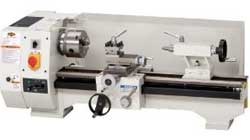
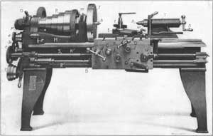
The standard “engine” lathe, which is the type commonly used by machinists for doing general work, is one of the most important tools in a machine shop, because it is adapted to a great variety of operations, such as turning all sorts of cylindrical and taper parts, boring holes, cutting threads, etc. The illustration Fig. 1 shows a lathe which, in many respects, represents a typical design, and while some of the parts are arranged differently on other makes, the general construction is practically the same as on the machine illustrated.

Fig. 1. Bradford Belt-driven Lathe—View of Front or Operating Side
The principal parts are the bed B, the headstock H, the tailstock T, and the carriage C. The headstock contains a spindle which is rotated by a belt that passes over the cone-pulley P, and this spindle rotates the work, which is usually held between pointed or conical centers h and h1 in the headstock and tailstock, or in a chuck screwed onto the spindle instead of the faceplate F. The carriage C can be moved lengthwise along the bed by turning handle d, and it can also be moved by power, the movement being transmitted from the headstock spindle either through gears a, b, c, and lead-screw S, or by a belt operating on pulleys p and p1, which drive the feed-rod R. The lead-screw S is used when cutting threads, and the feed-rod R for ordinary turning operations; in this way the wear on the lead-screw is reduced and its accuracy is preserved.
[2]On the carriage, there is a cross-slide D which can be moved at right angles to the lathe bed by handle e, and on D there is an upper or compound slide E which can be swiveled to different positions. The tool t, that does the turning, is clamped to the [3] upper slide, as shown, and it can be moved with relation to the work by the movement of the carriage C along the bed, or by moving slide D crosswise. The lengthwise movement is used to feed the tool along the work when turning, boring or cutting a screw, and the crosswise movement for facing the ends of shafts, etc., or for radial turning. When the tool is to be fed at an angle, other than at right angles to the bed, slide E, which can be set to the required angle, is used. The lengthwise and crosswise feeding movements can be effected by power, the lengthwise feed being engaged by tightening knob k, and the cross-feed by tightening knob l. The direction of either of these movements can also be reversed by shifting lever r. Ordinarily the carriage and slide are adjusted by hand to bring the tool into the proper position for turning to the required diameter, and then the power feed (operating in the desired direction) is engaged. The tailstock T can be clamped in different positions along the bed, to suit the length of the work, and its center h1 can be moved in or out for a short distance, when adjusting it to the work, by turning handle n.
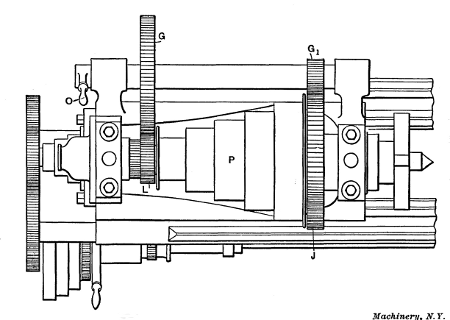
Fig. 2. Plan View of Lathe Headstock showing Back-gears
As some metals are much harder than others, and as the[4] diameters of parts to be turned also vary considerably, speed changes are necessary, because if the speed is excessive, the turning tool will become dull in too short a time. These speed changes (with a belt-driven lathe) are obtained by placing the driving belt on different steps of cone-pulley P, and also by the use of back-gears. The cone-pulley can be connected directly with the spindle or be disengaged from it by means of bolt m. When the pulley and spindle are connected, five speeds (with this particular lathe) are obtained by simply shifting the driving belt to different steps of the cone. When a slower speed is required than can be obtained with the belt on the largest step of the cone, the latter is disconnected from the spindle, and the back-gears G and G1 (shown in the plan view Fig. 2) are moved forward into mesh by turning handle O; the drive is then from cone-pulley P and gear L to gear G, and from gear G1 to the large gear J on the spindle. When driving through the back-gears, five more speed changes are obtained by shifting the position of the driving belt, as before. The fastest speed with the back-gears in mesh is somewhat slower than the slowest speed when driving direct or with the back-gears out of mesh; hence, with this particular lathe, a series of ten gradually increasing speeds is obtained. Changes of feed for the turning[5] tool are also required, and these are obtained by shifting the belt operating on pulleys p and p1 to different-sized steps. On some lathes these feed changes are obtained through gears which can be shifted to give different ratios. Many lathes also have gears in the headstock for changing the speeds.
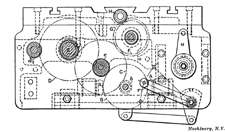
Fig. 3. Feed Mechanism of Lathe Apron
Front and rear views of the carriage apron, which contains the feeding mechanism, are shown in Figs. 3 and 4, to indicate how the feeds are engaged and reversed. The feed-rod R (Fig. 1) drives the small bevel gears A and A1 (Figs. 3 and 4), which are mounted on a slide S that can be moved by lever r to bring either bevel gear into mesh with gear B. Gear B is attached to pinion b (see Fig. 3) meshing with gear C, which, when knob k (Fig. 1) is tightened, is locked by a friction clutch to pinion c. The latter pinion drives gear D which rotates shaft E. A pinion cut on the end of shaft E engages rack K (Fig. 1) attached to the bed, so that the rotation of E (which is controlled by knob k) moves the carriage along the bed. To reverse the direction of the movement, it is only necessary to throw gear A into mesh and gear A1 out, or vice versa, by operating lever r. When the carriage is traversed by hand, shaft E and gear D are rotated by pinion d1 connected with handle d (Fig. 1).
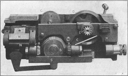
Fig. 4. Rear View of Lathe Apron
The drive for the cross-feed is from gear C to gear F which [6] can be engaged through a friction clutch (operated by knob l, Fig. 1) with gear G meshing with a pinion H. The latter rotates the cross-feed screw, which passes through a nut attached to slide D (Fig. 1), thus moving the latter at right angles to the ways of the bed. The cross-feed is also reversed by means of lever r. As previously explained, lead-screw S is only used for feeding the carriage when cutting threads. The carriage is engaged with this screw by means of two half-nuts N (Fig. 4) that are free to slide vertically and are closed around the screw by operating lever u. These half-nuts can only be closed when lever r is in a central or neutral position, so that the screw feed and the regular turning feed cannot be engaged at the same time. As previously mentioned, lead-screw S, Fig. 1, is rotated from the lathe spindle, through gears a, b and c, called change gears. An assortment of these gears, of various sizes, is provided with the lathe, for cutting screws of different pitch. The gears to use for any pitch within the range of the lathe are given on the plate I.
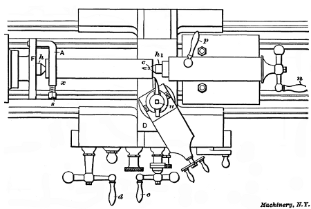
Fig. 5. Plan View showing Work Mounted between Centers of Lathe
Example of Cylindrical Turning.—Having now considered the principal features of what might be called a standard lathe, the method of using it in the production of machine parts will be explained. To begin with a simple example of work, suppose a steel shaft is to be turned to a diameter of 21/4 inches and a length of 141/2 inches, these being the finished dimensions. We will assume that the rough stock is cut off to a length of 145/8 inches and has a diameter of 25/8 inches. The first step in this operation is to form conically shaped center-holes in each end of the piece as indicated at c in Fig. 5. As all work of this kind is held, while being turned, between the centers h and h1, holes corresponding in shape to these centers are necessary to keep the work in place. There are several methods of forming these center-holes, as explained later.
After the work is centered, a dog A is clamped to one end by tightening screw s; it is then placed between the centers of the lathe. The dog has a projecting end or “tail,” as it is commonly called, which enters a slot in the faceplate F and thereby drives [7] or rotates the work, when power is applied to the lathe spindle onto which the faceplate is screwed. The tailstock center h1, after being oiled, should be set up just tight enough to eliminate all play, without interfering with a free rotary movement of the work. This is done by turning handle n, and when the center is properly adjusted, the tailstock spindle containing the center is locked by tightening handle p. (Ordinary machine oil is commonly used for lubricating lathe centers, but a lubricant having more “body” should be used, especially when turning heavy parts. The following mixtures are recommended: 1. Dry or powdered red lead mixed with a good grade of mineral oil to the consistency of cream. 2. White lead mixed with sperm oil with enough graphite added to give the mixture a dark lead color.)
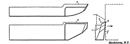
Fig. 6. Lathe Side-tool for Facing Ends of Shafts, etc.
Facing the Ends Square with a Side-tool.—Everything is now ready for the turning operation. The ends of the piece should be faced square before turning the body to size, and the tool for this squaring operation is shown in Fig. 6; this is known as a side-tool. It has a cutting edge e which shaves off the metal as indicated in the end view by the dotted lines. The side f is ground to an angle so that when the tool is moved in the direction shown by the arrow, the cutting edge will come in contact with the part to be turned; in other words, side f is[8] ground so as to provide clearance for the cutting edge. In addition, the top surface against which the chip bears, is beveled to give the tool keenness so that it will cut easily. As the principles of tool grinding are treated separately in Chapter II we shall for the present consider the tool's use rather than its form.
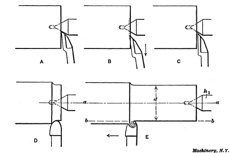
Fig. 7. Facing End with Side-tool and Turning Work Cylindrical
For facing the end, the side tool is clamped in the toolpost by tightening the screw u, Fig. 5, and it should be set with the cutting edge slightly inclined from a right-angled position, the point being in advance so that it will first come into contact with the work. The cutting edge should also be about the same height as the center of the work. When the tool is set, the lathe (if belt-driven) is started by shifting an overhead belt and the tool is then moved in until the point is in the position shown at A, Fig. 7. The tool-point is then fed against the end by handle d, Fig. 5, until a light chip is being turned off, and then it is moved outward by handle e (as indicated by the arrow at B, Fig. 7), the carriage remaining stationary. As the movement of the tool-point is guided by the cross-slide D, which is at right angles with the axis of the work, the end will be faced square. For short turning operations of this kind, the power feeds ordinarily are not used as they are intended for comparatively long cuts. If it were necessary to remove much metal from the end, a number of cuts would be taken across it; in this case, however, the rough stock is only 1/8 inch too long so that this end need only be made true.
After taking a cut as described, the surface, if left rough by[9] the tool-point, should be made smooth by a second or finishing cut. If the tool is ground slightly round at the point and the cutting edge is set almost square, as at C, Fig. 7, a smooth finish can be obtained; the cut, however, should be light and the outward feed uniform. The work is next reversed in the centers and the driving dog is placed on the end just finished; the other end is then faced, enough metal being removed to make the piece 141/2 inches long, as required in this particular case. This completes the facing operation. If the end of the work does not need to be perfectly square, the facing operation can be performed by setting the tool in a right-angled position and then feeding it sidewise, thus removing a chip equal to the width of one side. Evidently this method is confined to comparatively small diameters and the squareness of the turned end will be determined by the position of the tool's cutting edge.
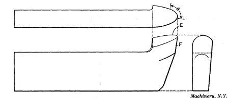
Fig. 8. Tool used for Cylindrical Turning
Turning Tool—Turning Work Cylindrical.—The tool used to turn the body to the required diameter is shaped differently from the side-tool, the cutting edge E of most tools used for plain cylindrical turning being curved as shown in Fig. 8. A [10] tool of this shape can be used for a variety of cylindrical turning operations. As most of the work is done by that part of the edge marked by arrow a, the top of the tool is ground to slope back from this part to give it keenness. The end F, or the flank, is also ground to an angle to provide clearance for the cutting edge. If the tool did not have this clearance, the flank would rub against the work and prevent the cutting edge from entering the metal. This type of tool is placed about square with the work, for turning, and with the cutting end a little above the center.
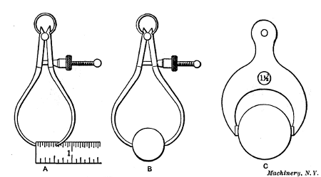
Fig. 9. Setting Calipers by Scale—Setting by Gage—Fixed Gage
Before beginning to turn, a pair of outside calipers or a micrometer should be set to 21/4 inches, which, in this case, is the finished diameter of the work. Calipers are sometimes set by using a graduated scale as at A, Fig. 9, or they can be adjusted to fit a standard cylindrical gage of the required size as at B. Very often fixed caliper gages C are used instead of the adjustable spring calipers. These fixed gages, sometimes called “snap” gages, are accurately made to different sizes, and they are particularly useful when a number of pieces have to be turned to exactly the same size.
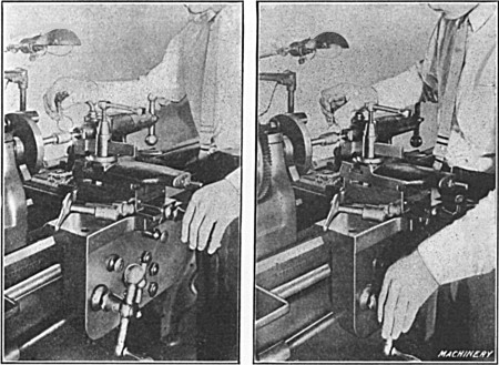
Fig. 10. Views showing how the Cross-slide and Carriage are Manipulated
by
Hand when Starting a Cut—
View to Left, Feeding Tool Laterally;
View to
Right, Feeding Tool in a Lengthwise Direction
The turning tool is started at the right-hand end of the work and the tool should be adjusted with the left hand when beginning a cut, as shown in Fig. 10, in order to have the right hand free for calipering. A short space is first turned by hand feeding, as at D, Fig. 7, and when the calipers show that the diameter is slightly greater than the finished size (to allow for a light finishing cut, either in the lathe or grinding machine) the power feed for the carriage is engaged; the tool then moves along the work, reducing it as at E. Evidently, if the movement is along a line b—b, parallel with the axis a—a, the diameter d will be the same at all points, and a true cylindrical piece will be turned. On the other hand, if the axis a—a is inclined one way or the other, the work will be made tapering; in fact, the tailstock center h1 can be adjusted laterally for turning tapers, but for straight turning, both centers must be in alignment with the carriage travel. Most lathes have lines on the stationary and movable parts of the tailstock base which show when the centers are set for straight turning. These lines, however, may not be absolutely correct, and it is good practice to test the alignment of the centers before beginning to turn. This can be done by taking trial cuts, at each end of the work (without disturbing the tool's crosswise position), and then comparing the diameters, or by testing the carriage travel with a true cylindrical piece held between the centers as explained later.
If the relative positions of the lathe centers are not known, the work should be calipered as the cut progresses to see if the diameter d is the same at all points. In case the diameter gradually increases, the tailstock center should be shifted slightly to the rear before taking the next cut, but if the diameter gradually diminishes, the adjustment would, of course, be made in the opposite direction. The diameter is tested by attempting to pass the calipers over the work. When the measuring points just touch the work as they are gently passed across it, the diameter being turned is evidently the same as the size to which the calipers are set.
As the driving dog is on one end, the cut cannot be taken over the entire length, and when the tool has arrived at say position x, Fig. 5, it is returned to the starting point and the work is reversed in the centers, the dog being placed upon the other end. The unfinished part is then turned, and if the cross-slide is not moved, the tool will meet the first cut. It is not likely that the two cuts will be joined or blended together perfectly, however, and for this reason a cut should be continuous when this is possible.
Roughing and Finishing Cuts.—Ordinarily in lathe work, as well as in other machine work, there are two classes of cuts, known as “roughing” and “finishing” cuts. Roughing cuts are for reducing the work as quickly as possible almost to the required size, whereas finishing cuts, as the name implies, are intended to leave the part smooth and of the proper size. When the rough stock is only a little larger than the finished diameter, a single cut is sufficient, but if there is considerable metal to turn away, one or more deep roughing cuts would have to be taken, and, finally, a light cut for finishing. In this particular case, one roughing and one finishing cut would doubtless be taken, as the diameter has to be reduced 3/8 inch. Ordinarily the roughing cut would be deep enough to leave the work about 1/32 or perhaps 1/16 inch above the finished size. When there is considerable metal to remove and a number of roughing cuts have to be taken, the depth of each cut and the feed of the tool are governed largely by the pulling power of the lathe and the strength of the work to withstand the strain of a heavy cut. The depth of roughing cuts often has to be reduced considerably because the part being turned is so flexible that a heavy cut would spring the work and cause the tool to gouge in. Of course, just as few cuts as possible should be taken in order to save time. The speed of the work should also be as fast as the conditions will allow for the same reason, but as there are many things which govern the speed, the feed of the tool, and the depth of the cut, these important points are referred to separately in Chapter II.
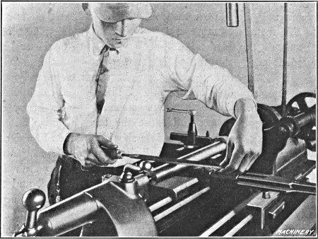
Fig. 11. Filing Work after Finishing Cut is taken
Filing and Finishing.—In many cases the last or finishing cut does not leave as smooth a surface as is required and it is necessary to resort to other means. The method commonly employed for finishing in the lathe is by the use of a file and emery cloth. The work is rotated considerably faster for filing than for turning, and the entire surface is filed by a flat, single-cut file, held as shown in Fig. 11. The file is passed across the work and advanced sidewise for each forward stroke, until the entire surface is finished. The file should be kept in contact with the work continually, but on the return stroke the pressure should be relieved. The movement of the file during the forward or cutting stroke should be much slower than when filing in a vise. By moving the file slowly, the work can make a number of revolutions for each stroke, which tends to keep it round, as practically the same amount of metal is removed from the entire circumference. On the other hand, short rapid strokes tend to produce flat spots, or at least an irregular surface, especially if the work can only make part of a revolution for each cutting stroke. The pressure on the file during the forward stroke should also be kept as nearly uniform as possible.
It is very difficult to file a part smooth and at the same time to keep it round and cylindrical, and the more filing that has to be done, the greater the chance of error. For this reason, the amount left for filing should be very small; in fact, the metal removed by filing should be just enough to take out the tool marks and give a smooth finish. Very often a satisfactory finish can be obtained with a turning tool, and filing is not necessary at all. The file generally used for lathe work is a “single-cut bastard” of “mill” section, having a length of from 12 to 14 inches.
Sometimes particles of metal collect between the teeth of a file and make deep scratches as the file is passed across the work. When this occurs, the teeth should be cleaned by using a wire brush or a file card, which is drawn across the file in the direction of the teeth. This forming of tiny particles between the teeth is known as “pinning” and it can sometimes be avoided by rubbing chalk on the file. Filing is not only done to obtain a smooth finish, but also to reduce the work to an exact diameter, as a very slight reduction can be made in this way.
If a polish is desired, this can be obtained by holding a piece of emery cloth tightly around the work as it revolves. The coarseness of emery cloth is indicated by letters and numbers corresponding to the grain number of loose emery. The letters and numbers for grits ranging from fine to coarse are as follows: FF, F, 120, 100, 90, 80, 70, 60, 54, 46, 40. For large work roughly filed, use coarse cloth such as Nos. 46 or 54, and then finer grades to obtain the required polish. If the work has been carefully filed, a good polish can be obtained with Nos. 60 and 90 cloth, and a brilliant polish by finishing with No. 120 and flour-emery.
Most cylindrical parts can be finished more quickly and accurately in the grinder than in the lathe, and many classes of work are, at the present time, simply rough-turned in the lathe and then ground to size in a cylindrical grinding machine.
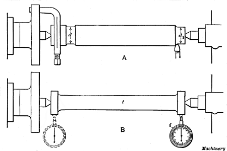
Fig. 12. Two Methods of Aligning Centers for Cylindrical Turning
Aligning Centers for Cylindrical Turning.—Whena rod or shaft must be turned cylindrical or to the same diameter throughout its entire length, it is good practice to test the alignment of the centers, before inserting the work. The position of the tailstock center for cylindrical turning may be indicated by the coincidence of graduation marks on the base, but if accuracy is necessary, the relative position of the two centers should be determined in a more positive way. A very simple and convenient method of testing the alignment is shown at A in Fig. 12. The work is first turned for a short distance, near the dogged end, as shown, and the tool is left as set for this cut; then the tailstock center is withdrawn and the work is moved sufficiently to permit running the tool back to the tailstock end without changing its original setting. A short cut is then taken at this end and the diameters d and d1 are carefully compared. In case there is any variation, the tailstock center is adjusted laterally, other trial cuts are taken, and the test repeated.
Another method is illustrated at B, which requires the use of a test-bar t. This bar should have accurately made centers and the ends finished to exactly the same diameter. The lathe centers are aligned by placing the bar between them and then testing the position of the ends. This can be done by comparing each end with a tool held in the toolpost and moved from one to the other by shifting the carriage, but a better method is to clamp a test indicator i in the toolpost and bring it in contact with first one end of the bar and then the other. If the dial does not register the same at each end, it shows that the lathe centers are not in line. Even when centers are correctly set, lathes that have been in use a long time do not always turn cylindrical or straight, because if the ways that guide the carriage are worn unevenly, the tool as it moves along does not remain in the same plane and this causes a variation in the diameter of the part being turned.
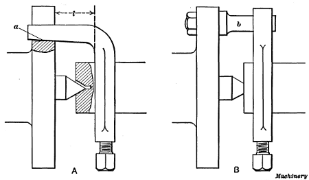
Fig. 13. (A) Dog that is too Short for Faceplate.
(B) Straight Driving Dog
Application of Drivers or Dogs.—Work that is turned between centers is sometimes driven by a dog which is so short for the faceplate that the bent driving end bears against the bottom a of the faceplate slot, as shown at A, Fig. 13. If the dog is nearly the right length, it may allow the headstock center to enter the center in the work part way, with the result that the turned surface is not true with the centers. When a driving dog of this type is used, care should be taken to see that it moves freely in the faceplate slot and does not bind against the bottom. By using a straight dog (B), which is driven by a pin b bolted to the faceplate, all danger from this source is eliminated. The straight dog, however, is used more particularly to do away with the leverage l of a bent dog, as this leverage tends to spring a flexible part when a cut is being taken.
Straight dogs are also made with two driving ends which engage pins on opposite sides of the faceplate. This type is preferable because it applies the power required for turning, evenly to the work, which still further reduces the tendency to spring it out of shape. The principal objection to the double-ended type lies in the difficulty of adjusting the driving pins so that each bears with equal pressure against the dog. The double-ended driver is often used for large work especially if deep roughing cuts are necessary.
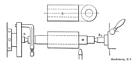
Fig. 14. Bushing mounted on Arbor for Turning
Lathe Arbors or Mandrels.—When it is necessary to turn the outside of a part having a hole through it, centers cannot, of course, be drilled in the ends and other means must be resorted to. We shall assume that the bushing B, Fig. 14, has a finished hole through the center, and it is desired to turn the outside cylindrical and concentric with the hole. This could be done by forcing a tightly-fitted arbor M, having accurately-centered ends, into the bushing and inserting the mandrel and work between the lathe centers h and h1 as shown. Evidently, if the arbor runs true on its centers, the hole in the bushing will also run true and the outside can be turned the same as though the arbor and bushing were a solid piece. From this it will be seen that an arbor simply forms a temporary support for parts that are bored and therefore cannot be centered.
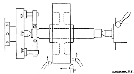
Fig. 15. Turning Pulley Held on an Arbor
Another example of work that would be turned on an arbor is shown in Fig. 15. This is a small cast-iron wheel having a finished hole through the hub, and the outer surface and sides of the rim are to be turned true with this hole. In this case, the casting would also be held by pressing a mandrel through the hub; as shown. This method, however, would only apply to comparatively small wheels because it would be difficult, if not impossible, to prevent a large wheel from turning on the arbor when taking a cut, and even if it could be driven, large work could be done to better advantage on another type of machine. (The vertical boring mill is used extensively for turning large wheels, as explained in Chapter VI.) When turning the outside of the rim, a tool similar to that shown at t should be used, but for facing or turning the sides, it might be better, if not necessary, to use tools having bent ends as shown by the dotted lines; in fact, turning tools of various kinds are made with the ends bent to the right or left, as this enables them to be used on surfaces that could not be reached very well with a straight tool. If a comparatively large pulley is mounted near the end of the arbor, it can be driven directly by pins attached to the faceplate and engaging the pulley arms. This method of driving is often employed when the diameter to be turned is large and the hole for the arbor is so small that there will not be sufficient friction for driving.
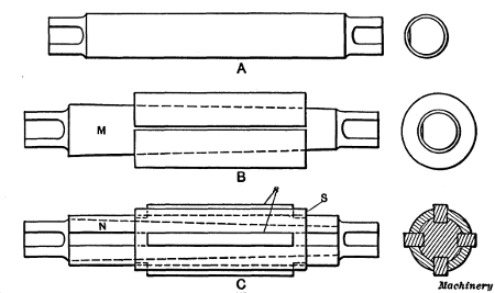
Fig. 16. Different Types of Lathe Arbors
Different Types of Lathe Arbors.—Three different types of lathe arbors are shown in Fig. 16. The kind shown at A is usually made of tool steel and the body is finished to a standard size. The ends are somewhat reduced and flat spots are milled, as shown, to give the clamping screw of the dog a good grip. The body of the arbor is usually tapered about 0.006 inch per foot. This taper makes it easier to insert the arbor in a close-fitting hole, and it also permits slight variations in the diameter of different holes. As to hardening, the practice at the present time among manufacturers is to harden arbors all over, but for extremely accurate work, an arbor having hardened ends and a soft body is generally considered superior, as there is less tendency of distortion from internal stresses. Hardened arbors are “seasoned” before finish-grinding to relieve these internal stresses.
The solid type A, Fig. 16, is used very extensively, but in shops where a great variety of work is being done and there are many odd-sized holes, some form of expanding arbor B can be used to advantage. This type, instead of being solid, consists of a tapering inner arbor M on which is placed a split bushing that can be expanded, within certain limits, by driving in the tapering member. The advantage of this type is that a comparatively small stock of arbors is required, as different-sized bushings can be used. This type can also be fitted to holes of odd sizes, whereas a solid arbor must be provided for each different size hole, unless the variation is very slight. The latter are, however, more accurate than the expanding type.
Another form of expanding arbor is shown at C. This type has a straight body N in which four tapering grooves are cut lengthwise, as shown, and there is a sleeve S, containing four slots that are located to correspond with the tapering grooves. Strips s are fitted into these slots, and as the part N is driven in, the strips are moved outward as they ascend the tapering grooves. By having different sets of these strips of various heights, one arbor of this type can be made to cover quite a range of sizes. It is not suited, however, to thin work, as the pressure, being concentrated in four places, would spring a flexible part out of shape.
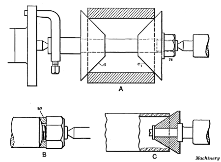
Fig. 17. (A) Cone Arbor.
(B) Nut Arbor.
(C) Pipe Center
The cone arbor or mandrel shown at A, in Fig. 17, is convenient for holding parts having comparatively large holes, as it can be adjusted for quite a range of diameters. The work is gripped between the two cones c and c1 which are forced together by nut n. The cones are prevented from turning upon the arbor by keys. This style of arbor should not be used for accurate work. The threaded arbor B is used for facing the sides of nuts square with the tapped hole. When a nut is first put upon the arbor, the rough side comes against an equalizing washer w. This washer rests against a spherical seat so that it can shift to provide a uniform bearing for the rough side of the nut, even though it is not square with the tapped hole. This feature prevents the nut from being canted on the arbor and insures an accurately faced nut. The revolving conical center shown at C is often used for holding a pipe or tube while turning the outside. The cone is adjusted to fit into the hole of the pipe, by means of the tailstock spindle, and the opposite end is usually held in a chuck.
Particular care should be taken to preserve the accuracy of the centers of lathe arbors by keeping them clean and well-oiled while in use.
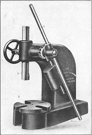
Mandrel or Arbor Press.—The best method of inserting an arbor of the solid type in a hole is by using a press, Fig. 18, designed for that purpose, but if such a press is not available and it is necessary to drive the mandrel in, a “soft” hammer, made of copper, lead or other soft material, should be used to protect the centered end of the arbor. In either case, the arbor should not be forced in too tightly, for if it fits properly, this will not be necessary in order to hold the work securely. On the other hand, the work might easily be broken by attempting to force the arbor in as far and as tightly as possible. In using the arbor press, the work is placed on the base B with the hole in a vertical position, and the arbor (which should be oiled slightly) is forced down into it by ram R, operated by lever L. Slots are provided in the base, as shown, so that the end of the arbor can come through at the bottom of the hole. The lever of this particular press is counter-weighted so that it rises to a vertical position when released. The ram can then be adjusted quickly to any required height by the handwheel seen at the left.
Some shops are equipped with power-driven mandrel or arbor presses. This type is particularly desirable for large work, owing to the greater pressure required for inserting mandrels that are comparatively large in diameter. One well-known type of power press is driven by a belt, and the downward pressure of the ram is controlled by a handwheel. The ram is raised or lowered by turning this handwheel in one direction or the other, and a gage shows how much pressure is being applied. This type of press can also be used for other purposes, such as forcing bushings or pins into or out of holes, bending or straightening parts, or for similar work.
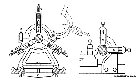
Steadyrest for Supporting Flexible Parts.—Occasionally long slender shafts, rods, etc., which have to be turned, are so flexible that it is necessary to support them at some point between the lathe centers. An attachment for the lathe known as a steadyrest is often used for this purpose. A steadyrest is composed of a frame containing three jaws J (Fig. 19), that can be adjusted in or out radially by turning screws S. The frame is hinged at h, thus allowing the upper half to be swung back (as shown by the dotted lines) for inserting or removing the work. The bolt-clamp c holds the hinged part in the closed position. The base of the frame has V-grooves in it that fit the ways of the lathe bed. When the steadyrest is in use, it is secured to the bed by clamp C, and the jaws J are set in against the work, thus supporting or steadying it during the turning operation. The steadyrest must, of course, be located at a point where it will not interfere with the turning tool.
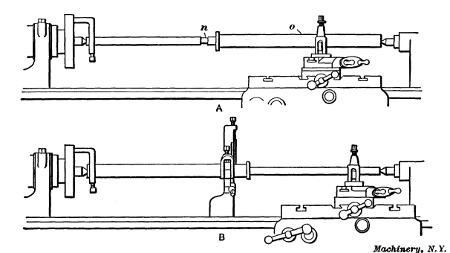
Fig. 20 shows the application of the steadyrest to a long forged rod, having one small end, which makes it too flexible to be turned without support. As this forging is rough, a true surface n a little wider than the jaws J (Fig. 19) is first turned as a bearing for the jaws. This should be done very carefully to prevent the work from mounting the tool. A sharp pointed tool should be used and very light cuts taken. The steadyrest is next clamped to the lathe bed opposite the turned surface, and the jaws are adjusted in against this surface, thus forming a bearing. Care should be taken not to set up the jaws too tightly, as the work should turn freely but without play. The large part of the rod and central collar are then turned to size, this half being machined while the small part is in the rough and as stiff as possible. The rod is then reversed and the steadyrest is applied to the part just finished, as shown at B, thus supporting the work while the small end is being turned. That part against which the jaws bear should be kept well oiled, and if the surface is finished it should be protected by placing a strip of emery cloth beneath the jaws with the emery side out; a strip of belt leather is also used for this purpose, the object in each case being to prevent the jaws from scratching and marring the finished surface, as they tend to do, especially if at all rough.
If the work were too flexible to permit turning a spot at n, this could be done by first “spotting” it at some point o, and placing the steadyrest at that point while turning another spot at n.
Sometimes it is desirable to apply a steadyrest to a surface that does not run true and one which is not to be turned; in such a case a device called a “cat-head” is used. This is simply a sleeve S (Fig. 21) which is placed over the untrue surface to serve as a bearing for the steadyrest. The sleeve is made to run true by adjusting the four set-screws at each end, and the jaws of the steadyrest are set against it, thus supporting the work.
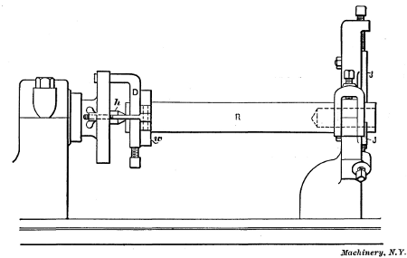
Fig. 22. Shaft supported by Steadyrest for Drilling and Boring End
Application of Steadyrest when Boring.—Another example illustrating the use of the steadyrest is shown in Fig. 22. The rod R is turned on the outside and a hole is to be bored in the end (as shown by dotted lines) true with the outer surface. If the centers used for turning the rod are still in the ends, as they would be ordinarily, this work could be done very accurately by the following method: The rod is first placed between the centers as for turning, with a driving dog D attached, and the steadyrest jaws J are set against it near the outer end, as shown.
Before any machine work is done, means must be provided for holding the rod back against the headstock center h, because, for an operation of this kind, the outer end cannot be supported by the tailstock center; consequently the work tends to shift to the right. One method of accomplishing this is shown in the illustration. A hardwood piece w, having a hole somewhat larger than the work, is clamped against the dog, in a crosswise position, by the swinging bolts and thumb-screws shown. If the dog is not square with the work, the wood piece should be canted so that the bearing will not be all on one side. For large heavy parts a similar “bridle” or “hold-back”—as this is commonly called—is made by using steel instead of wood for the part w. Another very common method which requires no special equipment is illustrated in Fig. 23. An ordinary leather belt lacing L is attached to the work and faceplate while the latter is screwed off a few turns as shown. Then the lacing is drawn up by hand and tied, and the faceplate is screwed onto the spindle, thus tightening the lacing and drawing the work against the headstock center. The method of applying the lacing is quite clearly indicated in the illustration. If a small driving faceplate is used, it may be necessary to drill holes for the belt lacing, as shown.
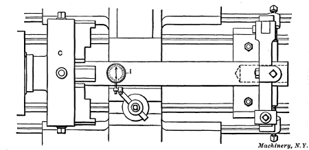
Fig. 24. Testing Work with Dial Indicator
A hole is next drilled in the end of the rod by using a twist drill in the tailstock. If the hole is finished by boring, a depth mark should be made on the tool shank that will warn the workman of the cutting end's approach to the bottom. A chuck can also be used in connection with a steadyrest for doing work of this kind, as shown in Fig. 24, the end of the rod being held and driven by the chuck C. If the piece is centered, it can be held on these centers while setting the steadyrest and adjusting the chuck, but if the ends are without centers, a very good way is to make light centers in the ends with a punch; after these are properly located they are used for holding the work until the steadyrest and chuck jaws have been adjusted. In case it is necessary to have the end hole very accurate with the outside of the finished rod, a test indicator I should be applied to the shaft as shown. This is an instrument which shows with great accuracy whether a rotating part runs true and it is also used for many other purposes in machine shops. The indicator is held in the lathe toolpost and the contact point beneath the dial is brought against the work. If the latter does not run true, the hand of the indicator vibrates and the graduations on the dial show how much the work is out in thousandths of an inch.
The Follow-rest.—When turning long slender parts, such as shafts, etc., a follow-rest is often used for supporting the work. The follow-rest differs from the steadyrest in that it is attached to and travels with the lathe carriage. The type illustrated to the right in Fig. 19 has two adjustable jaws which are located nearly opposite the turning tool, thus providing support where it is most needed. In using this rest, a cut is started at the end and the jaws are adjusted to this turned part. The tool is then fed across the shaft, which cannot spring away from the cut because of the supporting jaws. Some follow-rests have, instead of jaws, a bushing bored to fit the diameter being turned, different bushings being used for different diameters. The bushing forms a bearing for the work and holds it rigidly. Whether a bushing or jaws are used, the turning tool is slightly in advance of the supporting member.
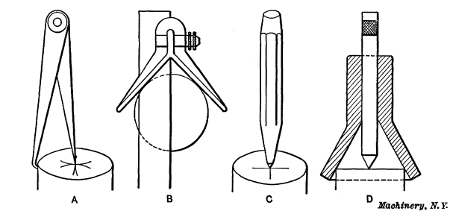
Fig. 25. Centering End with Punch preparatory to Drilling
Centering Parts to be Turned.—As previously mentioned, there are a number of different methods of forming center-holes in the ends of parts that have to be turned while held between lathe centers. A method of centering light work, and one that requires few special tools, is first to locate a central point on the end and then drill and ream the center-hole by using the lathe itself. Hermaphrodite dividers are useful for finding the center, as illustrated at A, Fig. 25, but if the work is fairly round, a center-square B is preferable. A line is scribed across the end and then another line at right angles to the first by changing the position of the square; the intersection of these two lines will be the center, which should be marked by striking a pointed punch C with a hammer. If a cup or bell center-punch D is available, it will not be necessary to first make center lines, as the conical part shown locates the punch in a central position. This style of punch should only be used on work which is fairly round.
After small centers have been located in both ends, their position can be tested by placing the work between the lathe centers and rotating it rapidly by drawing the hand quickly across it. By holding a piece of chalk close to the work as it spins around, a mark will be made on the “high” side if the centers are not accurate; the centers are then shifted toward these marks. If the work is close to the finished diameter, the centers should, of course, be located quite accurately in order that the entire surface of the work will be turned true when it is reduced to the finished size.
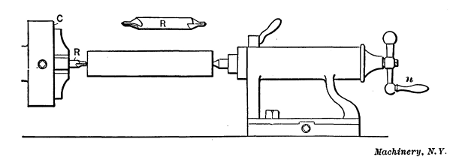
Fig. 26. Drilling Centers in the Lathe
One method of forming these center-holes is indicated in Fig. 26. A chuck C is screwed onto the spindle in place of the faceplate, and a combination center drill and reamer R is gripped by the chuck jaws and set to run true. The center is then drilled and reamed at one end by pressing the work against the revolving drill with the tailstock spindle, which is fed out by turning handle n. The piece is then reversed for drilling the opposite end. The work may be kept from revolving while the centers are being drilled and reamed, by attaching a dog to it close to the tailstock end and then adjusting the cross-slide until the dog rests upon the slide. Many parts can be held by simply gripping them with one hand. From the foregoing it will be seen that the small centers made by punch C, Fig. 25, serve as a starting point for the drill and also as a support for the outer end of the work while the first hole is being drilled.
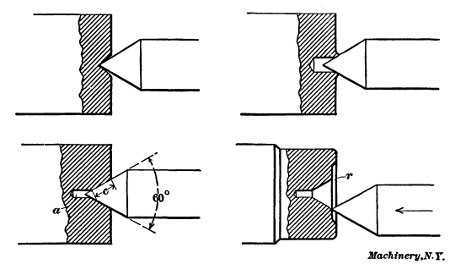
Fig. 27. Centers of Incorrect and Correct Form
The form of center-hole produced by a combination drill and reamer is shown by the lower left-hand view in Fig. 27. A small straight hole a in the bottom prevents the point of the lathe center from coming in contact with the work and insures a good bearing on the conical surface c. The standard angle for lathe centers is sixty degrees, as the illustration shows, and the tapering part of all center-holes should be made to this angle.
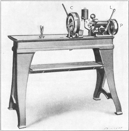
Fig. 28. Special Machine for Centering Parts to be Turned
Centering Machine.—Many shops have a special machine for forming centers which enables the operation to be performed quickly. One type of centering machine is shown in Fig. 28. The work is gripped in a chuck C that automatically locates it in a central position so that it is not necessary to lay out the end before drilling. There are two spindles s, one of which holds the drill and the other the countersink, and these are rotated by a belt passing over pulley P. Each of these spindles is advanced by lever L and either of them can be moved to a position central with the work, as they are mounted in a swiveling frame. In operating this machine, a small straight hole is first made by a twist drill held in one of the spindles; the other spindle is then moved over to the center and the hole is reamed tapering. The arrangement is such that neither spindle can be advanced by the feeding lever except when in a central position. The amount that each spindle can be advanced is limited by a fixed collar inside the head, and there is also a swinging adjustable stop against which the end of the work should be placed before tightening the chuck. These two features make it possible to ream center holes of the same size or depth in any number of pieces.
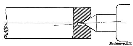
Fig. 29. The Imperfect Center Bearing is the Result of Centering before Straightening
Different Forms of Centers.—In some poorly equipped shops it is necessary to form centers by the use of a center-punch only, as there is no better tool. If the end of the punch has a sixty-degree taper, a fair center can be formed in this way, but it is not a method to be recommended, especially when accurate work is required. Sometimes centers are made with punches that are too blunt, producing a shallow center, such as the one shown in the upper left-hand view, Fig. 27. In this case all the bearing is on the point of the lathe center, which is the worst possible place for it. Another way is to simply drill a straight hole as in the upper view to the right; this is also bad practice in more than one respect. The lower view to the right shows a form of center which is often found in the ends of lathe arbors, the mouth of the center being rounded, at r, and the arbor end recessed as shown. The rounded corner prevents the point of the lathe center from catching when it is moved rapidly towards work which is not being held quite centrally (as shown by the illustration), and the end is recessed to protect the center against bruises. Stock that is bent should always be straightened before the centers are drilled and reamed. If the work is first centered and then straightened the bearing on the lathe center would be as shown in Fig. 29. The center will then wear unevenly with the result that the surfaces last turned will not be concentric with those which were finished first.
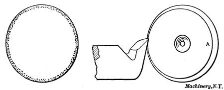
Fig. 30. Tool Steel should be centered Concentric, in order to remove the Decarbonized Outer Surface
Precaution When Centering Tool Steel.—Ordinarily centers are so located that the stock runs approximately true before being turned, but when centering tool steel to be used in making tools, such as reamers, mills, etc., which need to be hardened, particular care should be taken to have the rough surface run fairly true. This is not merely to insure that the piece will “true-up,” as there is a more important consideration, the disregard of which often affects the quality of the finished tool. As is well known, the degree of hardness of a piece of tool steel that has been heated and then suddenly cooled depends upon the amount of carbon that it contains, steel that is high in carbon becoming much harder than that which contains less carbon. Furthermore, the amount of carbon found at the surface, and to some little depth below the surface of a bar of steel, is less than the carbon content in the rest of the bar. This is illustrated diagrammatically in Fig. 30 by the shaded area in the view to the left. (This decarbonization is probably due to the action of the oxygen of the air on the bar during the process of manufacture.) If stock for a reamer is so centered that the tool removes the decarbonized surface only on one side, as illustrated to the right, evidently when the reamer is finished and hardened the teeth on the side A will be harder than those on the opposite side, which would not have been the case if the rough bar had been centered true. To avoid any trouble of this kind, stock that is to be used for hardened tools should be enough larger than the finished diameter and so centered that this decarbonized surface will be entirely removed in turning.
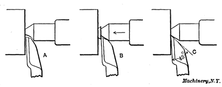
Fig. 31. Three Methods of Facing the Ends Square
Facing the Ends of Centered Stock.—As a piece of work is not properly centered until the ends are faced square, we will consider this operation in connection with centering. Some machinists prefer lathe centers that are cut away as shown at A, Fig. 31, so that the point of the side tool can be fed in far enough to face the end right up to the center hole. Others, instead of using a special center, simply loosen the regular one slightly and then, with the tool in a position as at B, face the projecting teat by feeding both tool and center inward as shown by the arrow. Whenever this method is employed, care should be taken to remove any chips from the center hole which may have entered. A method which makes it unnecessary to loosen the regular center, or to use a special one, is to provide clearance for the tool-point by grinding it to an angle of approximately forty-five degrees, as shown at C. If the tool is not set too high, it can then be fed right up to the lathe center and the end squared without difficulty. As for the special center A, the use of special tools and appliances should always be avoided unless they effect a saving in time or their use makes it possible to accomplish the same end with less work.
Truing Lathe Centers.—The lathe centers should receive careful attention especially when accurate work must be turned. If the headstock center does not run true as it revolves with the work, a round surface may be turned, but if the position of the driving dog with reference to the faceplate is changed, the turned surface will not run true because the turned surface is not true with the work centers. Furthermore, if it is necessary to reverse the work for finishing the dogged or driving end, the last part turned will be eccentric to the first. Therefore, the lathe centers should be kept true in order to produce turned surfaces that are true or concentric with the centered ends, as it is often necessary to change the part being turned “end for end” for finishing, and any eccentricity between the different surfaces would, in many cases, spoil the work.
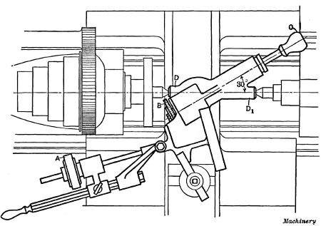
Fig. 32. Grinder for Truing Lathe Centers
Some lathes are equipped with hardened centers in both the head-and tailstock and others have only one hardened center which is in the tailstock. The object in having a soft or unhardened headstock center is to permit its being trued by turning, but as a soft center is quite easily bruised and requires truing oftener than one that is hard, it is better to have both centers hardened. Special grinders are used for truing these hardened centers. One type that is very simple and easily applied to a lathe is shown in Fig. 32. This grinder is held in the lathe toolpost and is driven by a wheel A that is held in contact with the cone-pulley. The emery wheel B is moved to a position for grinding by adjusting the carriage and cross-slide, and it is traversed across the conical surface of the center by handle C. As the grinding proceeds, the wheel is fed inward slightly by manipulating the cross-slide.
This grinder is set to the proper angle by placing the two centered ends D and D1 between the lathe centers, which should be aligned as for straight turning. The grinding spindle will then be 30 degrees from the axis of the lathe spindle. The grinder should be carefully clamped in the toolpost so that it will remain as located by the centered ends. After the tailstock center is withdrawn, the emery wheel is adjusted for grinding. As the wheel spindle is 30 degrees from the axis of the lathe spindle, the lathe center is not only ground true but to an included angle of 60 degrees, which is the standard angle for lathe centers. There are many other styles of center grinders on the market, some of which are driven by a small belt from the cone-pulley and others by electric motors which are connected with ordinary lighting circuits. The tailstock center is ground by inserting it in the spindle in place of the headstock center. Before a center is replaced in its spindle, the hole should be perfectly clean as even a small particle of dirt may affect the alignment. The center in the headstock is usually referred to as the “live center” because it turns around when the lathe is in use, and the center in the tailstock as the “dead center,” because it remains stationary.
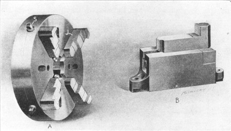
Fig. 33. (A) Lathe Chuck.
(B) Faceplate Jaw
Universal, Independent and Combination Chucks.—Many parts that are turned in the lathe are so shaped that they cannot be held between the lathe centers like shafts and other similar pieces and it is often necessary to hold them in a chuck A, Fig. 33, which is screwed onto the lathe spindle instead of the faceplate. The work is gripped by the jaws J which can be moved in or out to accommodate various diameters. There are three classes of chucks ordinarily used on the lathe, known as the independent, universal and combination types. The independent chuck is so named because each jaw can be adjusted in or out independently of the others by turning the jaw screws S with a wrench. The jaws of the universal chuck all move together and keep the same distance from the center, and they can be adjusted by turning any one of the screws S, whereas with the independent type the chuck wrench must be applied to each jaw screw. The combination chuck, as the name implies, may be changed to operate either as an independent or universal type. The advantage of the universal chuck is that round and other parts of a uniform shape are located in a central position for turning without any adjustment. The independent type is, however, preferable in some respects as it is usually stronger and adapted for holding odd-shaped pieces because each jaw can be set to any required position.
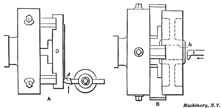
Fig. 34. (A) Radial Facing.
(B) Boring Pulley Held in Chuck
Application of Chucks.—As an example of chuck work, we shall assume that the sides of disk D, Fig. 34, are to be turned flat and parallel with each other and that an independent chuck is to be used. First the chuck is screwed onto the lathe spindle after removing the faceplate. The chuck jaws are then moved out or in, as the case may be, far enough to receive the disk and each jaw is set about the same distance from the center by the aid of concentric circles on the face of the chuck. The jaws are then tightened while the disk is held back against them to bring the rough inner surface in a vertical plane. If the work is quite heavy, it can be held against the chuck, before the jaws are tightened, by inserting a piece of wood between it and the tailstock center; the latter is then run out far enough to force the work back. The outside or periphery of the disk should run nearly true and it may be necessary to move the jaws in on one side and out on the other to bring the disk to a central position. To test its location, the lathe is run at a moderate speed and a piece of chalk is held near the outer surface. If the latter runs out, the “high” side will be marked by the chalk, and this mark can be used as a guide in adjusting the jaws. It should be remembered that the jaws are moved only one-half the amount that the work runs out.
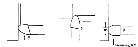
Fig. 35. Tools Ground so that Top Slopes away from Working Part of Cutting Edge
A round-nosed tool t of the shape shown can be used for radial facing or turning operations of the kind illustrated. This tool is similar to the form used when turning between centers, the principal difference being in the direction of the top slope. The radial facing tool should be ground to slope downward toward a (see Fig. 35) whereas the regular turning tool slopes toward b, the inclination in each case being away from that part of the cutting edge which does the work. The cutting edge should be the same height as the lathe centers, and the cut is taken by feeding the tool from the outside in to the center. The cut is started by hand and then the power feed is engaged, except for small surfaces. The first cut should, if possible, be deep enough to get beneath the scale, especially if turning cast iron, as a tool which just grazes the hard outer surface will be dulled in a comparatively short time.
If it were simply necessary to turn a true flat surface and the thickness of the disk were immaterial, two cuts would be sufficient, unless the surface were very uneven, the first or roughing cut being followed by a light finishing cut. For a finishing cut, the same tool could be used, but if there were a number of disks to be faced, a square-nosed tool F, Fig. 35, could probably be used to better advantage. This type has a broad flat cutting edge that is set parallel with the rough-turned surface and this broad edge enables a coarse feed to be taken, thus reducing the time required for the finishing cut. If a coarse feed were taken with the round tool, the turned surface would have spiral grooves in it, whereas with the broad cutting edge, a smooth surface is obtained even though the feed is coarse. The amount of feed per revolution of the work, however, should always be less than the width w of the cutting edge. Very often broad tools cannot be used for finishing cuts, especially when turning steel, because their greater contact causes chattering and results in a rough surface. An old and worn lathe is more liable to chatter than one that is heavy and well-built, and as the diameter of the work also makes a difference, a broad tool cannot always be used for finishing, even though, theoretically, it would be preferable. After one side of the disk is finished, it is reversed in the chuck, the finished surface being placed against the jaws. The remaining rough side is then turned, care being taken when starting the first cut to caliper the width of the disk at several points to make sure that the two sides are parallel.
Example of Boring.—Another example of chuck work is shown at B, Fig. 34. In this case a cast-iron pulley is to have a true hole h bored through the hub. (The finishing of internal cylindrical surfaces in a lathe is referred to as boring rather than turning.) The casting should be set true by the rim instead of by the rough-cored hole in the hub; this can be done by the use of chalk as previously explained. Even though a universal type of chuck were used, the jaws of which, as will be recalled, are self-centering, it might be necessary to turn the pulley relative to the chuck as a casting sometimes runs out because of rough spots or lumps which happen to come beneath one or more of the jaws.
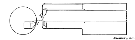
The shape of tool t for boring is quite different from one used for outside turning, as shown by Fig. 36. The cutting end of a solid type of tool is forged approximately at right angles to the body or shank, and the top surface is ground to slope away from the working part w of the cutting edge, as with practically all turning tools. The front part or flank, f is also ground away to give the edge clearance. This type of tool is clamped in the toolpost with the body about parallel with the lathe spindle, and ordinarily the cutting edge would be about as high as the center of the hole, or a little below, if anything. When starting a cut, the tool is brought up to the work by moving the carriage and it is then adjusted radially to get the right depth of cut, by shifting the cross-slide. The power feed for the carriage is then used, the tool feeding back through the hole as indicated by the arrow, Fig. 34. In this case, as with all turning operations, the first cut should be deep enough to remove the hard outer scale at every part of the hole. Usually a rough-cored hole is so much smaller than the finished size that several cuts are necessary; in any case, the last or finishing cut should be very light to prevent the tool from springing away from the work, so that the hole will be as true as possible. Boring tools, particularly for small holes, are not as rigid as those used for outside turning, as the tool has to be small enough to enter the hole and for this reason comparatively light cuts have to be taken. When boring a small hole, the largest tool that will enter it without interference should be used to get the greatest rigidity possible.
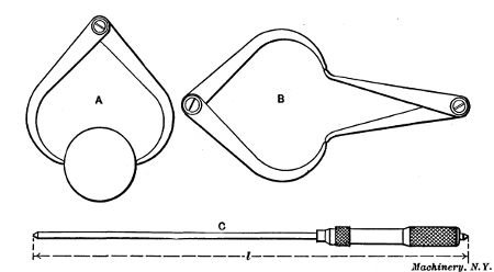
Fig. 37 (A) Setting Outside Calipers.
(B) Transferring Measurements to
Inside Calipers.
(C) Micrometer Gage
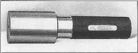
Fig. 38. Standard Plug Gage
Measuring Bored Holes.—The diameters of small holes that are being bored are usually measured with inside calipers or standard gages. If the pulley were being bored to fit over some shaft, the diameter of the shaft would first be measured by using outside calipers, as shown at A, Fig. 37, the measuring points of the calipers being adjusted until they just made contact with the shaft when passed over it. The inside calipers are then set as at B to correspond with the size of the shaft, and the hole is bored just large enough to admit the inside calipers easily. Very accurate measurements can be made with calipers, but to become expert in their use requires experience. Some mechanics never become proficient in the art of calipering because their hands are “heavy” and they lack the sensitiveness and delicacy of touch that is necessary. For large holes, a gage C is often used, the length l being adjusted to the diameter desired. Small holes are often bored to fit hardened steel plug gages (Fig. 38), the cylindrical measuring ends of which are made with great accuracy to standard sizes. This type of gage is particularly useful when a number of holes have to be bored to the same size, all holes being made just large enough to fit the gage without any perceptible play.

Fig. 39. Diagram Illustrating Importance of Setting Work with Reference to Surfaces to be Turned
Setting Work in the Chuck.—When setting a part in a chuck, care should be taken to so locate it that every surface to be turned will be true when machined to the finished size. As a simple illustration, let us assume that the hole through the cast-iron disk, Fig. 39, has been cored considerably out of center, as shown. If the work is set by the outside surface S, as it would be ordinarily, the hole is so much out of center that it will not be true when bored to the finished size, as indicated by the dotted lines. On the other hand, if the rough hole is set true, the outside cannot be finished all over, without making the diameter too small, when it is finally turned. In such a case, the casting should be shifted, as shown by the arrow, to divide the error between the two surfaces, both of which can then be turned as shown by the dotted lines in the view to the right. This principle of dividing the error when setting work can often be applied in connection with turning and boring. After a casting or other part has been set true by the most important surface, all other surfaces which require machining should be tested to make sure that they all can be finished to the proper size.
Inaccuracy from Pressure of Chuck Jaws.—Work that is held in a chuck is sometimes sprung out of shape by the pressure of the chuck jaws so that when the part is bored or turned, the finished surfaces are untrue after the jaws are released and the work has resumed its normal shape. This applies more particularly to frail parts, such as rings, thin cylindrical parts, etc. Occasionally the distortion can be prevented by so locating the work with relation to the chuck jaws that the latter bear against a rigid part. When the work cannot be held tightly enough for the roughing cuts without springing it, the jaws should be released somewhat before taking the finishing cut, to permit the part to spring back to its natural shape.
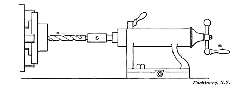
Fig. 40. Drilling in the Lathe
Drilling and Reaming.—When a hole is to be bored from the solid, it is necessary to drill a hole before a boring tool can be used. One method of drilling in the lathe is to insert an ordinary twist drill in a holder or socket S, Fig. 40, which is inserted in the tailstock spindle in place of the center. The drill is then fed through the work by turning the handle n and feeding the spindle outward as shown by the arrow. Before beginning to drill, it is well to turn a conical spot or center for the drill point so the latter will start true. This is often done by using a special tool having a point like a flat drill. This tool is clamped in the toolpost with the point at the same height as the lathe centers. It is then fed against the center of the work and a conical center is turned. If the drill were not given this true starting point, it probably would enter the work more or less off center. Drills can also be started without turning a center by bringing the square end or butt of a tool-shank held in the toolpost in contact with the drill near the cutting end. If the point starts off center, thus causing the drill to wobble, the stationary tool-shank will gradually force or bump it over to the center.
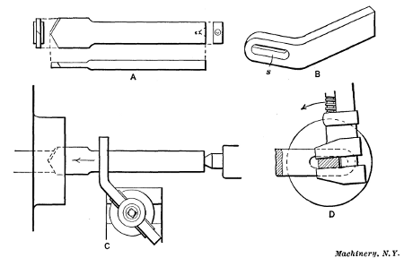
Fig. 41. Flat Drill and Holder
Small holes are often finished in the lathe by drilling and reaming without the use of a boring tool. The form of drill that is used quite extensively for drilling cored holes in castings is shown in Fig. 41, at A. This drill is flat and the right end has a large center hole for receiving the center of the tailstock. To prevent the drill from turning, a holder B, having a slot s in its end through which the drill passes, is clamped in the toolpost, as at C. This slot should be set central with the lathe centers, and the drill, when being started, should be held tightly in the slot by turning or twisting it with a wrench as indicated in the end view at D; this steadies the drill and causes it to start fairly true even though the cored hole runs out considerably.
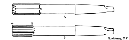
Fig. 42. Rose and Fluted Reamers
Another style of tool for enlarging cored holes is shown in Fig. 42, at A. This is a rose chucking reamer, having beveled cutting edges on the end and a cylindrical body, which fits closely in the reamed hole, thus supporting and guiding the cutting end. The reamer shown at B is a fluted type with cutting edges that extend from a to b; it is used for finishing holes and the drill or rose reamer preceding it should leave the hole very close to the required size. These reamers are held while in use in a socket inserted in the tailstock spindle, as when using a twist drill.
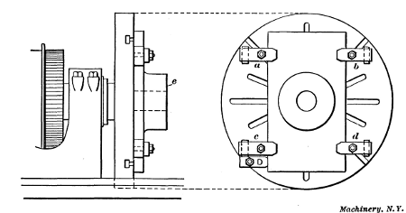
Fig. 43. Casting Clamped to Faceplate for Turning and Boring
Holding Work on Faceplate.—Some castings or forgings are so shaped that they cannot be held in a chuck very well, or perhaps not at all, and work of this kind is often clamped to a faceplate which is usually larger than the faceplate used for driving parts that are turned between the centers. An example of faceplate work is shown in Fig. 43. This is a rectangular-shaped casting having a round boss or projection, the end e of which is to be turned parallel with the back face of the casting previously finished on a planer. A rough cored hole through the center of the boss also needs to be bored true.
The best way to perform this operation in the lathe would be to clamp the finished surface of the casting directly against the faceplate by bolts and clamps a, b, c, and d, as shown; the work would then be turned just as though it were held in a chuck. By holding the casting in this way, face e will be finished parallel with the back surface because the latter is clamped directly against the true-running surface of the faceplate. If a casting of this shape were small enough it could also be held in the jaws of an independent chuck, but if the surface e needs to be exactly parallel with the back face, it is better to clamp the work to the faceplate. Most lathes have two faceplates: One of small diameter used principally for driving work turned between centers, and a large one for holding heavy or irregularly shaped pieces; either of these can be screwed onto the spindle, and the large faceplate has a number of slots through which clamping bolts can be inserted.
The proper way to clamp a piece to the faceplate depends, of course, largely on its shape and the location of the surface to be machined, but in any case it is necessary to hold it securely to prevent any shifting after a cut is started. Sometimes castings can be held by inserting bolts through previously drilled holes, but when clamps are used in connection with the bolts, their outer ends are supported by hardwood or metal blocks which should be just high enough to make the clamp bear evenly on the work. When deep roughing cuts have to be taken, especially on large diameters, it is well to bolt a piece to the faceplate and against one side of the casting, as at D, to act as a driver and prevent the work from shifting; but a driver would not be needed in this particular case. Of course a faceplate driver is always placed to the rear, as determined by the direction of rotation, because the work tends to shift backward when a cut is being taken. If the surface which is clamped against the faceplate is finished as in this case, the work will be less likely to shift if a piece of paper is placed between it and the faceplate.
Work mounted on the faceplate is generally set true by some surface before turning. As the hole in this casting should be true with the round boss, the casting is shifted on the faceplate until the rough outer surface of the boss runs true; the clamps which were previously set up lightly are then tightened. The face e is first turned by using a round-nosed tool. This tool is then replaced by a boring tool and the hole is finished to the required diameter. If the hole being bored is larger than the central hole in the faceplate, the casting should be clamped against parallel pieces, and not directly against the faceplate, to provide clearance for the tool when it reaches the inner end of the hole and prevent it from cutting the faceplate. The parallel pieces should be of the same thickness and be located near the clamps to prevent springing the casting.
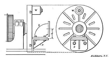
Fig. 44. Cast Elbow held on Angle-plate attached to Faceplate
Application of Angle-plate to Faceplate.—Another example of faceplate work is shown in Fig. 44. This is a cast-iron elbow E, the two flanges of which are to be faced true and square with each other. The shape of this casting is such that it would be very difficult to clamp it directly to the faceplate, but it is easily held on an angle-plate P, which is bolted to the faceplate. The two surfaces of this angle-plate are square with each other so that when one flange of the elbow is finished and bolted against the angle-plate, the other will be faced square. When setting up an angle-plate for work of this kind, the distance from its work-holding side to the center of the faceplate is made equal to the distance d between the center of one flange and the face of the other, so that the flange to be faced will run about true when bolted in place. As the angle-plate and work are almost entirely on one side of the faceplate, a weight W is attached to the opposite side for counterbalancing. Very often weights are also needed to counterbalance offset parts that are bolted directly to the faceplate. The necessity of counterbalancing depends somewhat upon the speed to be used for turning. If the surface to be machined is small in diameter so that the lathe can be run quite rapidly, any unbalanced part should always be counterbalanced.
Sometimes it is rather difficult to hold heavy pieces against the vertical surface of the faceplate while applying the clamps, and occasionally the faceplate is removed and placed in a horizontal position on the bench; the work can then be located about right, and after it is clamped, the faceplate is placed on the lathe spindle by the assistance of a crane.
Special faceplate jaws, such as the one shown to the right in Fig. 33, can often be used to advantage for holding work on large faceplates. Three or four of these jaws are bolted to the faceplate which is converted into a kind of independent chuck. These faceplate jaws are especially useful for holding irregularly shaped parts, as the different jaws can be located in any position.
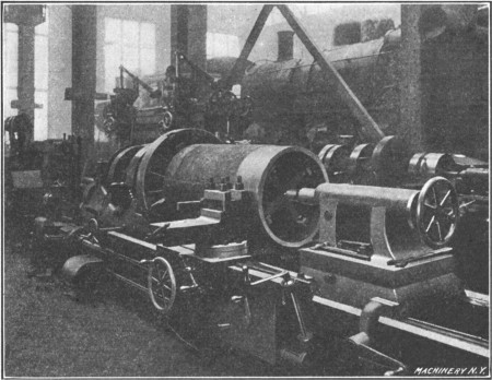
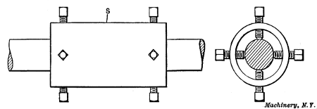
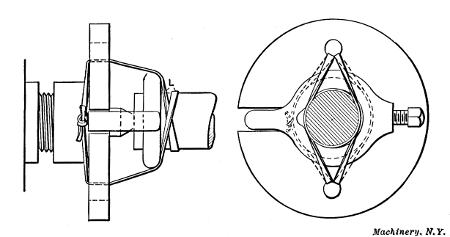
Fig. 45. Rough Turning a Cylinder Lining—Note Method of Supporting Outer End
Supporting Outer End of Chucked Work.—Fig. 45 shows how the tailstock center is sometimes used for supporting the outer end of a long casting, the opposite end of which is held in a chuck. This particular casting is to be turned and bored to make a lining for the cylinder of a locomotive in order to reduce the diameter of the cylinder which has been considerably enlarged by re-boring a number of times. These bushings are rough-turned on the outside while the outer end is supported by the cross-shaped piece or “spider” which forms a center-bearing for the tailstock. This spider has set screws in the flanged ends of the arms, which are tightened against the inner surface of the casting and are adjusted one way or the other in order to locate it in a concentric position. After roughing the outside, the inside is bored to the finish size; then centered disks, which fit into the bore, are placed in the ends of the bushing and the latter is finish-turned. The object in rough turning the outside prior to boring is to avoid the distortion which might occur if this hard outer surface were removed last.
Boring Large Castings in the Lathe.—An ordinary engine lathe is sometimes used for boring engine or pump cylinders, linings, etc., which are too large to be held in the chuck or on a faceplate, and must be attached to the lathe carriage. As a rule, work of this class is done in a special boring machine (see “Horizontal Boring Machines”), but if such a machine is not available, it may be necessary to use a lathe. There are two general methods of boring.
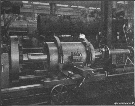
Fig. 46. Boring a Cylinder Lining in an Ordinary Engine Lathe
Fig. 46 shows how the lining illustrated in Fig. 45 is bored in a large engine lathe. The casting is held in special fixtures which are attached to the lathe carriage, and the boring-bar is rotated by the lathe spindle. The tool-head of this boring-bar carries two tools located 180 degrees apart and it is fed along the bar by a star-feed mechanism shown attached to the bar and the tailstock spindle. Each time the bar revolves, the star wheel strikes a stationary pin and turns the feed-screw which, as the illustration shows, extends along a groove cut in one side of the bar. This feed-screw passes through a nut attached to the tool-head so that the latter is slowly fed through the bore. When using a bar of this type, the carriage, of course, remains stationary.
Cylindrical parts attached to the carriage can also be bored by using a plain solid bar mounted between the centers. The bar must be provided with a cutter for small holes or a tool-head for larger diameters (preferably holding two or more tools)[51] and the boring is done by feeding the carriage along the bed by using the regular power feed of the lathe. A symmetrically shaped casting like a bushing or lining is often held upon wooden blocks bolted across the carriage. These are first cut away to form a circular seat of the required radius, by using the boring-bar and a special tool having a thin curved edge. The casting is then clamped upon these blocks by the use of straps and bolts, and if the curved seats were cut to the correct radius, the work will be located concentric with the boring-bar. When using a boring-bar of this type, the bar must be long enough to allow the part being bored to feed from one side of the cutter-head to the other, the cutter-head being approximately in a central location.
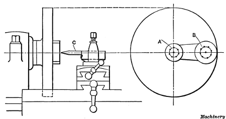
Fig. 47. Method of Setting Circle on Work Concentric with Lathe Spindle
Boring Holes to a Given Center Distance.—In connection with faceplate work, it is often necessary to bore two or more holes at a given distance apart. The best method of doing this may depend upon the accuracy required. For ordinary work sometimes two or more circles A and B (Fig. 47) are drawn upon the part to be bored, in the position for the holes; the piece is then clamped to the faceplate and one of the circles is centered with the lathe spindle by testing it with a pointer C held in the toolpost; that is, when the pointer follows the circle as the work is turned, evidently the circle is concentric with the spindle. The hole is then drilled and bored. The other circle is then centered in the same way for boring the second hole. As will be seen, the accuracy of this method depends first, upon the accuracy with which the circles were laid out, and second; upon the care taken in setting them concentric. For a more accurate way of locating parts for boring, see “Use of Center Indicator” and “Locating Work by the Button Method.”
Turning Brass, Bronze and Copper.—When turning soft yellow brass, a tool should be used having very little or no slope or rake on the top surface against which the chip bears, and for plain cylindrical turning, the point of the tool is drawn out quite thin and rounded, by grinding, to a radius of about 1/8 or 3/16 inch. If a tool having very much top slope is used for brass, there is danger of its gouging into the metal, especially if the part being turned is at all flexible. The clearance angle of a brass tool is usually about 12 or 14 degrees, which is 3 or 4 degrees greater than the clearance for steel turning tools. Most brass is easily turned, as compared with steel, and for that reason this increase in clearance is desirable, because it facilitates feeding the tool into the metal, especially when the carriage and cross-slide movements are being controlled by hand as when turning irregular shapes.
The speed for turning soft brass is much higher than for steel, being ordinarily between 150 and 200 feet per minute. When turning phosphor, tobin or other tough bronze compositions, the tool should be ground with rake the same as for turning steel, and lard oil is sometimes used as a lubricant. The cutting speed for bronzes varies from 35 or 40 to 80 feet per minute, owing to the difference in the composition of bronze alloys.
Turning tools for copper are ground with a little more top rake than is given steel turning tools, and the point should be slightly rounded. It is important to have a keen edge, and a grindstone is recommended for sharpening copper turning tools. Milk is generally considered the best lubricant to use when turning copper. The speed can be nearly as fast as for brass.
[53] Machining Aluminum.—Tools for turning aluminum should have acute cutting angles. After rough-grinding the tool, it is advisable to finish sharpening the cutting edge on a grindstone or with an oilstone for fine work, as a keen edge is very essential. High speeds and comparatively light cuts are recommended. The principal difficulty in the machining of aluminum and aluminum alloys is caused by the clogging of the chips, especially when using such tools as counterbores and milling cutters. This difficulty can be avoided largely by using the right kind of cutting lubricant. Soap-water and kerosene are commonly employed. The latter enables a fine finish to be obtained, provided the cutting tool is properly ground.
The following information on this subject represents the experience of the Brown-Lipe Gear Co., where aluminum parts are machined in large quantities: For finishing bored holes, a bar equipped with cutters has been found more practicable than reamers. The cutters used for machining 4-inch holes have a clearance of from 20 to 22 degrees and no rake or slope on the front faces against which the chips bear. The roughing cutters for this work have a rather sharp nose, being ground on the point to a radius of about 3/32 inch, but for securing a smooth surface, the finishing tools are rounded to a radius of about 3/4 inch. The cutting speed, as well as the feed, for machining aluminum is from 50 to 60 per cent faster than the speeds and feeds for cast iron. The lubricant used by this company is composed of one part “aqualine” and 20 parts water. This lubricant not only gives a smooth finish but preserves a keen cutting edge and enables tools to be used much longer without grinding. Formerly, a lubricant composed of one part of high-grade lard oil and one part of kerosene was used. This mixture costs approximately 30 cents per gallon, whereas the aqualine and water mixture now being used costs less than 4 cents per gallon, and has proved more effective than the lubricant formerly employed.