|
Turning and Boring on a Lathe
Online Reprint Chapter 7
This a complete book, published in
1914, divided into chapters on how to use a metal lathe, covering all
turning and boring operations.
|
Return to Contents
Turning and Boring
by Franklin D. Jones
Published by Industrial Press 1914
A special treatise for machinists students in industrial and
engineering schools, and apprentices on turning and boring methods
including modern practice with engine lathes, vertical, and horizontal
boring machines.
Shop Amazon.com
|
CHAPTER VII
HORIZONTAL BORING MACHINES
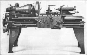
A boring machine of the horizontal type is shown in Fig. 1.
The construction and operation of this machine is very different from
that of a vertical boring mill and it is also used for an entirely
different class of work. The horizontal machine is employed principally
for boring, drilling or milling, whereas the vertical design is
especially adapted to turning and boring. The horizontal type is also
used for turning or facing flanges or similar surfaces when such an
operation can be performed to advantage in connection with other machine
work on the same part.
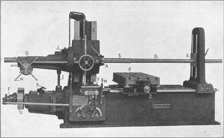
Fig. 1. Lucas Horizontal Boring, Drilling and Milling Machine
The type of machine illustrated in Fig. 1 has a heavy base or bed to which is bolted the column C having vertical ways on which the spindle-head H is mounted. This head contains a sleeve or quill in which the spindle S
slides longitudinally. The spindle carries cutters for boring, whereas
milling cutters or the auxiliary facing arm are bolted to the end A of the spindle sleeve. The work itself is attached either directly or indirectly to the table or platen P.
When the machine is in operation, the cutter or tool revolves with the
spindle sleeve or spindle and either the cutter or the part being
machined is given a feeding movement, depending on the character of the
work. The spindle can be moved in or out by hand for adjustment, or by
power for feeding the cutter, as when boring or drilling.
The entire spindle-head H can also be moved vertically on the face of the column C,
by hand, for setting the spindle to the proper height, or by power for
feeding a milling cutter in a vertical direction. When the vertical
position of the spindle-head is changed, the outboard bearing block B also moves up or down a corresponding amount, the two parts being connected by shafts and gearing. Block B
steadies the outer end of the boring-bar and the back-rest in which
this block is mounted can be shifted along the bed to suit the length of
the work, by turning the squared end of shaft D with a crank. The platen P has a cross-feed, and the saddle E
on which it is mounted can be traversed lengthwise on the bed; both of
these movements can also be effected by hand or power. There is a series
of power feeding movements for the cutters and, in addition, rapid
power movements in a reverse direction from the feed for returning a cutter quickly to its starting position, when this is desirable.
This machine is driven by a belt connecting pulley G with an
overhead shaft. When the machine is in operation, this pulley is
engaged with the main driving shaft by a friction clutch F controlled by lever L. This main shaft drives through gearing a vertical shaft I,
which by means of other gears in the spindle-head imparts a rotary
movement to the spindle. As a machine of this type is used for boring
holes of various diameters and for a variety of other work, it is
necessary to have a number of speed changes for the spindle. Nine speeds
are obtained by changing the position of the sliding gears controlled
by levers R and this number is doubled by back-gears in the spindle-head and controlled by lever J.
The amount of feed for the spindle, spindle-head, platen or saddle is varied by two levers K and K1
which control the position of sliding gears through which the feeding
movements are transmitted. The direction of the feed can be reversed by
shifting lever O. With this particular machine, nine feed changes
are available for each position of the spindle back-gears, making a
total of eighteen changes. The feeding movement is transmitted to the
spindle-head, spindle, platen or saddle, as required, by the three
distributing levers T, U and V, which control clutches connecting with the transmission shafts or feed screws. When lever T
is turned to the left, the longitudinal power feed for the spindle is
engaged, whereas turning it to the right throws in the vertical feed for
the spindle-head. Lever U engages the cross-feed for platen P and lever V, the longitudinal feed for saddle E.
These levers have a simple but ingenious interlocking device which
makes it impossible to engage more than one feed at a time. For example,
if lever T is set for feeding the spindle, levers U and V are locked against movement.
The feeds are started and stopped by lever M which also
engages the rapid power traverse when thrown in the opposite direction.
This rapid traverse operates for whatever feed is engaged by the
distributing levers and, as before stated, in a reverse direction. For
example, if the reverse lever O is set for feeding the spindle to the right, the rapid traverse would be to the left, and vice versa.
The cross-feed for the platen can be automatically tripped at any point
by setting an adjustable stop in the proper position and the feed can
also be tripped by a hand lever at the side of the platen.
All the different feeding movements can be effected by hand as well as by power. By means of handwheel N, the spindle can be moved in or out slowly, for feeding a cutter by hand. When the friction clamp Q is loosened, the turnstile W
can be used for traversing the spindle, in case a hand adjustment is
desirable. The spindle-head can be adjusted vertically by turning
squared shaft X with a crank, and the saddle can be shifted along the bed by turning shaft Y. The hand adjustment of the platen is effected by shaft Z. The spindle-head, platen and saddle can also be adjusted from the end of the machine, when this is more convenient. Shafts X, Y and Z
are equipped with micrometer dials which are graduated to show
movements of one-thousandth inch. These dials are used for accurately
adjusting the spindle or work and for boring holes or milling surfaces
that must be an exact distance apart.
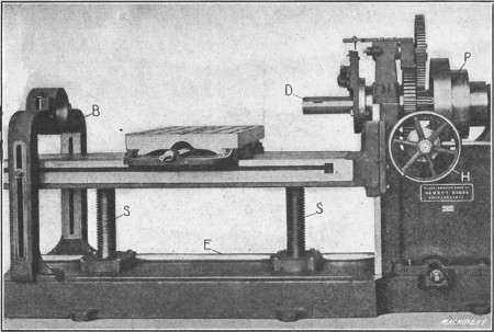
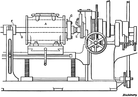
Fig. 2. Horizontal Boring and Drilling Machine with Vertical Table Adjustment
Horizontal Boring Machine with Vertical Table Adjustment.—Another horizontal boring machine is partly shown in Fig. 2.
This machine is of the same type as that illustrated in Fig. 1, but its
construction is quite different, as will be seen. The spindle cannot be
adjusted vertically as with the first design described, but it is
mounted and driven very much like the spindle of a lathe, and adjustment
for height is obtained by raising or lowering the work table. The
design is just the reverse, in this respect, of the machine shown in Fig. 1,
which has a vertical adjustment for the spindle, and a work table that
remains in the same horizontal plane. The raising or lowering of the
table is effected by shaft E, which rotates large nuts engaging the screws S. Shaft E is turned either by hand or power.
The main spindle is driven by a cone pulley P, either
directly, or indirectly through the back-gears shown. This arrangement
gives six spindle speeds, and double this number is obtained by using a
two-speed countershaft overhead. The motion for feeding the spindle
longitudinally is transmitted through a cone of gears, which gives the
required changes, to a pinion meshing with a rack which traverses the
spindle. The large handwheel H and a corresponding wheel on the
opposite side are used for adjusting the spindle rapidly by hand. The
yoke or outboard bearing B for the boring-bars can be clamped in any position along the bed for supporting the bar as close to the work as possible.
Horizontal boring machines are built in many other designs, but
they all have the same general arrangement as the machines illustrated
and operate on the same principle, with the exception of special types
intended for handling certain classes of work exclusively. The
horizontal boring, drilling and milling machine is very efficient for
certain classes of work because it enables all the machining operations
on some parts to be completed at one setting. To illustrate, a casting
which requires drilling, boring and milling at different places, can
often be finished without disturbing its position on the platen after it
is clamped in place. Frequently a comparatively small surface needs to
be milled after a part has been bored. If this milling operation can be
performed while the work is set up for boring, accurate results will be
obtained (provided the machine is in good condition) and the time saved
that would otherwise be required for re-setting the part on another
machine. Some examples of work on which different operations are
performed at the same setting will be referred to later. The horizontal
boring machine also makes it possible to machine duplicate parts without
the use of jigs, which is important, especially on large work, owing to
the cost of jigs.
Drilling and Boring—Cutters Used.—Holes are drilled in a horizontal machine by simply inserting a drill of required size either directly in the spindle S (see Fig. 1),
or in a reducing socket, and then feeding the spindle outward either by
hand or power. When a hole is to be bored, a boring-bar B1
is inserted in the spindle and the cutter is attached to this bar. The
latter is then fed through the hole as the cutter revolves. The
distinction made by machinists between drilling and boring is as
follows: A hole is said to be drilled when it is formed by sinking a
drill into solid metal, whereas boring means the enlargement of a
drilled or cored hole either by the use of a single boring tool, a
double-ended cutter which operates on both sides of the hole, or a
cutter-head having several tools.
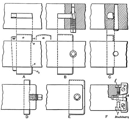
Fig. 3. Boring-cutters of Different Types
There are various methods of attaching cutters to boring-bars and
the cutters used vary for different classes of work. A simple style of
cutter which is used widely for boring small holes is shown at A in Fig. 3. The cutter c is made from flat stock and the cutting is done by the front edges e and e1, which are beveled in opposite directions. The cutter is held in the bar by a taper wedge w and it is centered by shoulders at s,
so that the diameter of the hole will equal the length across the
cutter. The outer corners at the front should be slightly rounded, as a
sharp corner would be dulled quickly. These cutters are made in
different sizes and also in sets for roughing and finishing. The
roughing cutter bores holes to within about 1/32
inch of the finish size and it is then replaced by the finishing
cutter. A cutter having rounded ends, as shown by the detail sketch a, is sometimes used for light finishing cuts. These rounded ends form the cutting edges and give a smooth finish.
Another method of holding a flat cutter is shown at B. The
conical end of a screw bears against a conical seat in, the cutter, thus
binding the latter in its slot. The conical seat also centers the
cutter. A very simple and inexpensive form of cutter is shown at C.
This is made from a piece of round steel, and it is held in the bar by a
taper pin which bears against a circular recess in the side of the
cutter. This form has the advantage of only requiring a hole through the
boring-bar, whereas it is necessary to cut a rectangular slot for the
flat cutter.
Fig. 4. Boring with a Flat Double-ended Cutter
Fig. 4 shows how a hole is bored by cutters of the type referred to. The bar rotates as indicated by the arrow a and at the same time feeds longitudinally as shown by arrow b.
The speed of rotation depends upon the diameter of the hole and the
kind of material being bored, and the feed per revolution must also be
varied to suit conditions. No definite rule can be given for speed or
feed. On some classes of work a long boring-bar is used, which passes
through the hole to be bored and is steadied at its outer end by the
back-rest B, Figs. 1 and 2.
On other work, a short bar is inserted in the spindle having a cutter
at the outer end. An inexpensive method of holding a cutter at the end
of a bar is shown at D, Fig. 3. The cutter
passes through a slot and is clamped by a bolt as shown. When it is
necessary to bore holes that are “blind” or closed at the bottom, a long
boring-bar which passes through the work cannot, of course, be used.
Sometimes it is necessary to have a cutter mounted at the extreme
end of a bar in order to bore close to a shoulder or the bottom of a
hole. One method of holding a cutter so that it projects beyond the end
of a bar is indicated at E. A screw similar to the one shown at B
is used, and the conical end bears in a conical hole in the cutter.
This hole should be slightly offset so that the cutter will be forced
back against its seat. The tool shown at F has adjustable cutters. The inner end of each cutter is tapering and bears against a conical-headed screw b which gives the required outward adjustment. The cutters are held against the central bolt by fillister-head screws f and they are clamped by the screws c.
Boring tools are made in many different designs and the number and form
of the cutters is varied somewhat for different kinds of work.
Fig. 5. Cutter-heads for Boring Large Holes
Cutter-heads for Boring Large Holes.—When large holes are to
be bored, the cutters are usually held in a cast-iron head which is
mounted on the boring-bar. One type of cutter-head is shown in Fig. 5. This particular head is double-ended and carries two cutters c.
The cutter-head is bored to fit the bar closely and it is prevented
from turning by a key against which a set-screw is tightened. By
referring to the end view, it will be seen that each cutter is offset
with relation to the center of the bar, in order to locate the front of
the tool on a radial line. The number of cutters used in a cutter-head
varies. By having several cutters, the work of removing a given amount
of metal in boring is distributed, and holes can be bored more quickly
with a multiple cutter-head, although more power is required to drive
the boring-bar. The boring-bar is also steadied by a multiple
cutter-head, because the tendency of any one cutter to deflect the bar
is counteracted by the cutters on the opposite side.
Fig. 6. Cutter-head with Four Boring Tools
A disk-shaped head having four cutters is illustrated in Fig. 6.
The cutters are inserted in slots or grooves in the face of the disk
and they are held by slotted clamping posts. The shape of these posts is
shown by the sectional view. The tool passes through an elongated slot
and it is tightly clamped against the disk by tightening nut n. This head is also driven by a key which engages a keyway in the boring-bar.
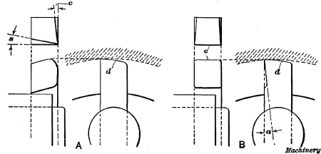
Fig. 7. Cutter-heads equipped with Adjustable Tools
Two other designs of cutter-heads are shown in Fig. 7. The one illustrated at A has three equally spaced cutters which are held in an inclined position. The cutters are clamped by screws c and they can be adjusted within certain limits by screws s.
The cutters are placed at an angle so that they will extend beyond the
front of the head, thus permitting the latter to be moved up close to a
shoulder. The cutter-heads shown in Figs. 5 and 6 can also be moved up close to a shoulder if bent cutters are used as shown in the right-hand view, Fig. 5.
The idea in bending the cutters is to bring the cutting edges in
advance of the clamping posts so that they will reach a shoulder before
the binding posts strike it. The arrangement of cutter-head B (Fig. 7) is clearly shown by the illustration.
Cutter-heads are often provided with two sets of cutters, one set
being used for roughing and the other for finishing. It is a good plan
to make these cutters so that the ends e (Fig. 6)
will rest against the bar or bottom of the slot, when the cutting edge
is set to the required radius. The cutters can then be easily set for
boring duplicate work. One method of making cutters in sets is to clamp
the annealed stock in the cutter-head and then turn the ends to the
required radius by placing the head in the lathe. After both sets of
cutters have been turned in this way, they are ground to shape and then
hardened.
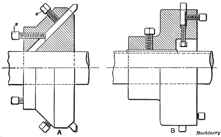
Fig. 8. Boring Tools for Roughing and Finishing Cuts
Boring cutters intended for roughing and finishing cuts are shown in the detail view Fig. 8 at A and B, respectively. The side of the roughing cutter A is ground to a slight angle c to provide clearance for the cutting edge, and the front has a backward slope s to give the tool keenness. This tool is a good form to use for roughing cuts in cast iron. The finishing tool at B has a broad flat edge e
and it is intended for coarse feeds and light cuts in cast iron. If a
round cutting edge is used for finishing, a comparatively fine feed is
required in order to obtain a smooth surface. The corners of tool B are rounded and they should be ground to slope inward as shown in the plan view. The top or ends d
of both of these tools are “backed off” slightly to provide clearance.
This clearance should be just enough to prevent the surface back of the
cutting edge from dragging over the work. Excessive end clearance not
only weakens the cutting edge, but tends to cause chattering. As a
finishing tool cuts on the upper end instead of on the side, the front
should slope backward as shown in the side view, rather than sidewise as
with a roughing cutter. The angle of the slope should be somewhat
greater for steel than cast iron, unless the steel is quite hard, thus
requiring a strong blunt tool.
Fig. 9. Cylinder mounted on Horizontal Machine for Boring
Cylinder Boring.—Fig. 9 illustrates
the use of a cutter-head for cylinder boring. After the cylinder casting
is set on the platen of the machine, the boring-bar with the
cutter-head mounted on it is inserted in the spindle. The bar B
has a taper shank and a driving tang similar to a drill shank, which
fits a taper hole in the end of the spindle. The cutter-head C is
fastened to the bar so that it will be in the position shown when the
spindle is shifted to the right, as the feeding movement (with this
particular machine) is to be in the opposite direction. The casting A should be set central with the bar by adjusting the work-table vertically and laterally, if necessary, and the outer support F should be moved close to the work, to make the bar as rigid as possible.
The cylinder is now ready to be bored. Ordinarily, one or two
roughing cuts and one finishing cut would be sufficient, unless the
rough bore were considerably below the finish diameter. As previously
explained, the speed and feed must be governed by the kind of material
being bored and the diameter of the cut. The power and rigidity of the
boring machine and the quality of the steel used for making the cutters
also affect the cutting speed and feed. As the finishing cut is very
light, a tool having a flat cutting edge set parallel to the bar is
ordinarily used when boring cast iron. The coarse feed enables the cut
to be taken in a comparatively short time and the broad-nosed tool gives
a smooth finish if properly ground.
The coarse finishing feed is not always practicable, especially if
the boring machine is in poor condition, owing to the chattering of the
tool, which results in a rough surface. The last or finishing cut should
invariably be a continuous one, for if the machine is stopped before
the cut is completed, there will be a ridge in the bore at the point
where the tool temporarily left off cutting. This ridge is caused by the
cooling and resulting contraction and shortening of the tool during the
time that it is stationary. For this reason independent drives are
desirable for boring machines.
Facing arms are attached to the bar on either side of the cylinder
for facing the flanges after the boring operation. The turning tool of a
facing arm is fastened to a slide which is fed outward a short distance
each revolution, by a star-wheel that is caused to turn as it strikes
against a stationary pin. By facing the flanges in this way, they are
finished square with the bore.
When setting a cylinder which is to be bored it should, when the
design will permit, be set true by the outside of the flange, or what is
even better, by the outside of the cylinder itself, rather than by the
rough bore, in order that the walls of the finished cylinder will have a
uniform thickness. The position of very large cylinders, while they are
being bored, is an important consideration. Such cylinders should be
bored in the position which they will subsequently occupy when
assembled. For example, the cylinder for a large horizontal engine
should be bored while in a horizontal position, as the bore is liable to
spring to a slight oval shape when the cylinder is placed horizontal
after being bored while standing in a vertical position. If, however,
the cylinder is bored while in the position in which it will be placed
in the assembled engine, this trouble is practically eliminated.
There is a difference of opinion among machinists as to the proper
shape of the cutting point of a boring tool for finishing cuts, some
contending that a wide cutting edge is to be preferred, while others
advocate the use of a comparatively narrow edge with a reduced feed. It
is claimed, that the narrow tool produces a more perfect bore, as it is
not so easily affected by hard spots in the iron, and it is also pointed
out that the minute ridges left by the narrow tool are an advantage
rather than a disadvantage, as they form pockets for oil and aid in
lubricating the cylinder. It is the modern practice, however, to use a
broad tool and a coarse feed for the light finishing cut, provided the
tool does not chatter.
The type of machine tool used for boring cylinders, and also the
method of procedure is determined largely by the size of the work and
the quantity which is to be machined. The turret lathe, as well as
horizontal and vertical boring mills, is used for this work, and in
automobile factories or other shops where a great many cylinders are
bored, special machines and fixtures are often employed.
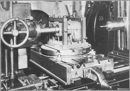
Fig. 10. Boring a Duplex Cylinder on a Horizontal Machine
Boring a Duplex Gasoline Engine Cylinder.—The method of
holding work on a horizontal boring machine depends on its shape. A
cylinder or other casting having a flat base can be clamped directly to
the platen, but pieces of irregular shape are usually held in special
fixtures. Fig. 10 shows how the cylinder casting of a gasoline engine is set up for the boring operation. The casting W is placed in a fixture F which is clamped to the machine table. One end of the casting rests on the adjustable screws S
and it is clamped by set-screws located in the top and sides of the
fixture. There are two cylinders cast integral and these are bored by a
short stiff bar mounted in the end of the spindle and having cutters at
the outer end. A long bar of the type which passes through the work and
is supported by the outboard bearing B, could not be used for this work, because the top of each cylinder is closed.
When one cylinder is finished the other is set in line with the
spindle by adjusting the work-table laterally. This adjustment is
effected by screw C, and the required center-to-center distance between the two cylinders can be gaged by the micrometer dial M
on the cross-feed screw, although positive stops are often used in
preference. After the first cylinder is bored, the dial is set to the
zero position by loosening the small knurled screw shown, and turning
the dial around. The feed screw is then rotated until the dial shows
that the required lateral adjustment is made, which locates the casting
for boring the second cylinder. The end of the casting is also faced
true by a milling cutter. Ordinarily, milling cutters are bolted
directly to the spindle sleeve A on this particular machine, which gives a rigid support for the cutter and a powerful drive.
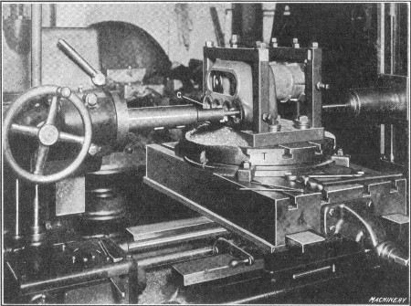
Fig. 11. Cylinder turned around for Machining Valve Seats
The next operation is that of boring and milling the opposite end
of the cylinder. This end is turned toward the spindle (as shown in Fig. 11) without unclamping the work or fixture, by simply turning the circular table T
half way around. This table is an attachment which is clamped to the
main table for holding work that must be turned to different positions
for machining the various parts. Its position is easily changed, and as
the work remains fixed with relation to the table, the alignment between
different holes or surfaces is assured, if the table is turned the
right amount. In this case, the casting needs to be rotated one-half a
revolution or 180 degrees, and this is done by means of angular
graduations on the base of the table. The illustration shows the casting
set for boring the inlet and exhaust valve chambers. The different
cutters required for boring are mounted on one bar as shown, and the
casting is adjusted crosswise to bring each valve chamber in position,
by using the micrometer dial. The single-ended cutter c forms a
shallow circular recess or seat in the raised pad which surrounds the
opening. The cover joint directly back of the cylinders is finished by
milling.
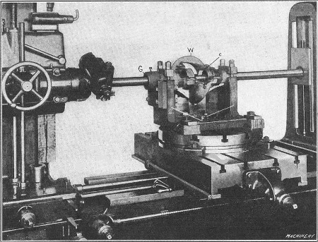
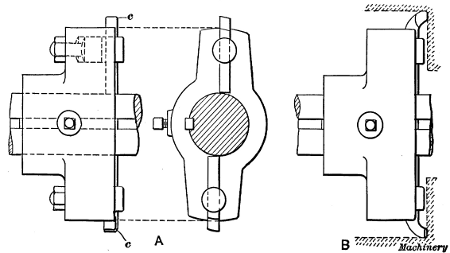
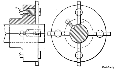
Fig. 12. Boring Differential Gear Casing
Examples of Boring, Radial Facing and Milling.—Another example of boring, in which the circular table is used, is shown in Fig. 12. The work W is a casing for the differential gears of an automobile. It is mounted in a fixture F
which is bolted to the table. The casting has round ends, which are
clamped in V-blocks, thus aligning the work. This fixture has a
guide-bushing G which is centered with the bar and cutter in
order to properly locate the casting. There is a bearing at each end of
the casing, and two larger ones in the center. These are bored by flat
cutters similar to the style illustrated at A in Fig. 3. The cutter for the inner bearings is shown at c.
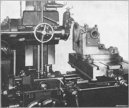
Fig. 13. Facing and Turning Flange of Differential Gear Casing
After the bearings are bored, the circular table is turned 90 degrees and the work is moved closer to the spindle (as shown in Fig. 13) for facing flange F
at right angles to the bearings. Circular flanges of this kind are
faced in a horizontal boring machine by a special facing-arm or head H.
For this particular job this head is clamped directly to the spindle
sleeve, but it can also be clamped to the spindle if necessary. The
turning tool is held in a slotted toolpost, and it is fed radially for
turning the side or face of the flange, by the well-known star feed at S. When this feed is in operation the bent finger E
is turned downward so that it strikes one of the star wheel arms for
each revolution; this turns the wheel slightly, and the movement is
transmitted to the tool-block by a feed-screw. The illustration shows
the tool set for turning the outside or periphery of the flange. This is
done by setting the tool to the proper radius and then feeding the work
horizontally by shifting the work-table along the bed. By referring to Fig. 12
it will be seen that the facing head does not need to be removed for
boring, as it is attached to the spindle driving quill and does not
interfere with the longitudinal adjustment of the spindle. This facing
head is also used frequently for truing the flanges of cylinders which
are to be bored, and for similar work.
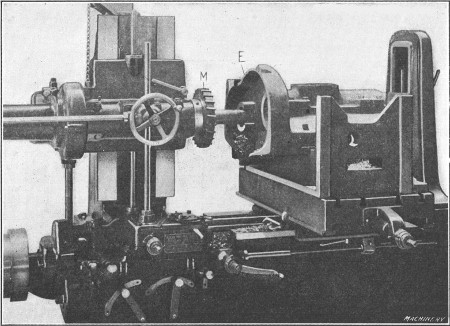
Fig. 14. Example of Work requiring Boring and Milling
Fig. 14 shows another example of work which
requires boring and milling. This casting is mounted on a fixture which
is bolted to the main table. In this case the circular table is not
necessary, because the work can be finished without swiveling it around.
After the boring is completed the edge E is trued by the large-face milling cutter M
bolted to the spindle sleeve. The irregular outline of the edge is
followed by moving the table crosswise and the spindle vertically, as
required.
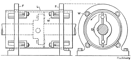
Fig. 15. Cylinder Lining mounted in Fixture for Boring
Fixture for Cylinder Lining or Bushing.—A method of holding a cylinder lining or bushing while it is being bored is shown in Fig. 15. The lining L is mounted in two cast-iron ring-shaped fixtures F.
These fixtures are circular in shape and have flat bases which are
bolted to the table of the machine. On the inside of each fixture, there
are four equally spaced wedges W which fit into grooves as shown
in the end view. These wedges are drawn in against the work by bolts,
and they prevent the lining from rotating when a cut is being taken.
This form of fixture is especially adapted for holding thin bronze
linings, such as are used in pump cylinders, because only a light
pressure against the wedges is required, and thin work can be held
without distorting it. If a very thin lining is being bored, it is well
to loosen the wedges slightly before taking the finishing cut, so that
the work can spring back to its normal shape.
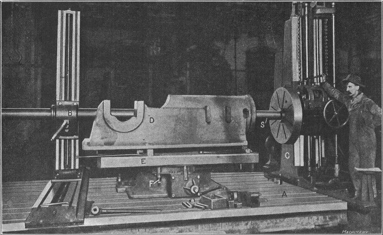
Fig. 16. Detrick & Harvey Horizontal Boring Machine of the Floor Type Boring Engine Bed Casting
Horizontal Boring Machine of Floor Type.—The type of horizontal boring, drilling and milling machine, shown in Fig. 16,
is intended for boring heavy parts such as the cylinders of large
engines or pumps, the bearings of heavy machine beds and similar work.
This machine can also be used for drilling and milling, although it is
intended primarily for boring, and the other operations are usually
secondary. This design is ordinarily referred to as the “floor type,”
because the work-table is low for accommodating large heavy castings.
The spindle S which drives the boring-bar, and the spindle
feeding mechanism, are carried by a saddle. This saddle is free to move
vertically on the face of column C which is mounted on transverse
ways extending across the right-hand end of the main bed. This
construction permits the spindle to move vertically or laterally (by
traversing the column) either for adjusting it to the required position
or for milling operations. The spindle also has a longitudinal movement
for boring. There is an outer bearing B for supporting the boring-bar, which also has lateral and vertical adjustments, so that it can be aligned with the bar.
The work done on a machine of this type is either clamped directly to the large bed-plate A
(which has a number of T-slots for receiving the heads of the clamping
bolts) or, in some cases, a special fixture may be used or an auxiliary
table. Boring machines of this same general construction are built in
many different sizes. The main spindle of the machine illustrated is
driven by a motor located at the rear of the vertical column C, the motion being transmitted to the spindle through shafts and gearing. The casting D,
shown in this particular illustration, is for a steam engine of the
horizontal type, and the operation is that of boring the cylindrical
guides or bearings for the crosshead. These bearings have a diameter of
153/4 inches and are 373/4
inches long. In boring them, two roughing cuts and one finishing cut
are taken. The end of the casting, which in the assembled engine bears
against the cylinder, is then faced by means of a regular facing arm.
After removing the boring-bar the table E of the special
fixture on which the casting is mounted is turned one quarter of a
revolution. A large milling cutter 24 inches in diameter is next mounted
on the spindle of the machine, and one side of the main bearing, as
well as the pads for the valve-rod guide-bar brackets, are milled. The
table is then revolved and the opposite side of the main bearing is
milled in the same way, the table being accurately located in the
different positions by an index plunger F which engages holes on
the under side. The spindle is now moved upward to allow the table to be
turned so as to locate the bearing end of the frame next to the
headstock of the machine. The milling cutter is then used to machine the
inside and top surfaces of the main bearing. By turning the fixture and
not changing the position of the casting after it is bolted into place,
the various surfaces are machined in the correct relation to one
another without difficulty. This is a good example of the work done on
horizontal boring machines of the floor type.
Return to Contents