|
Turning and
Boring on a Lathe
Online Reprint Chapter 3
This a complete book, published
in 1914, divided into chapters on how to use a metal lathe,
covering all turning and boring operations.
|
Return to Contents
Turning and Boring
by Franklin D. Jones
Published by Industrial Press 1914
A special treatise for machinists students in industrial and
engineering schools, and apprentices on turning and boring methods
including modern practice with engine lathes, vertical, and horizontal
boring machines.
Shop Amazon.com
|
CHAPTER 3
[1]
TAPER TURNING—SPECIAL OPERATIONS—FITTING
It is often necessary, in connection with lathe work, to turn
parts tapering instead of straight or cylindrical. If the work is
mounted between the centers, one method of turning a taper is
to set the tailstock center out of alignment with the headstock
center. When both of these centers are in line, the movement
of the tool is parallel to the axis of the work and, consequently, a
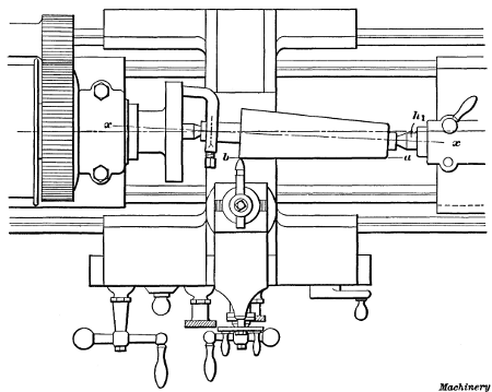
cylindrical surface is produced; but if the tailstock h1 is set out
of alignment, as shown in Fig. 1, the work will then be turned
tapering as the tool is traversed from a to b, because the axis
x—x is at an angle with the movement of the tool. Furthermore the
amount of taper or the difference between the diameters at the ends for
a given length, will depend on how much center h1 is set over from the central position.
Fig. 1. Taper Turning by the Offset-center Method
The amount of taper is usually given on drawings in inches
per foot, or the difference in the diameter at points twelve
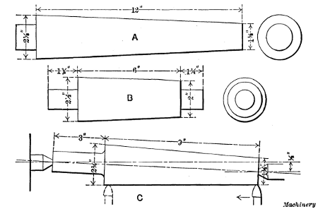
inches apart. For example, the taper of the piece shown at A,
Fig. 2, is 1 inch per foot, as the length of the tapering surface
is just twelve inches and the difference between the diameters
at the ends is 1 inch. The conical roller shown at B has a total
length of 9 inches and a tapering surface 6 inches long, and in
this case the taper per foot is also 1 inch, there being a difference
of 1/2 inch in a length
of 6 inches or 1 inch in twice that length. When the taper per foot is
known, the amount that the tailstock center should be set over for
turning that taper can easily be estimated, but it should be remembered
that the setting obtained in this way is not absolutely correct, and is
only intended to locate the center approximately. When a taper needs to
be at all accurate, it is tested with a gage, or by other means, after
taking a trial cut, as will be explained later, and the tailstock center
is readjusted accordingly. There are also more accurate methods of
setting the center, than by figuring the amount of offset, but as the
latter is often convenient this will be referred to first.
Fig. 2. Examples of Taper Work
Setting Tailstock Center for Taper Turning.—Suppose the
tailstock center is to be set for turning part C, Fig. 2, to a taper
of approximately 1 inch per foot. In this case the center would
simply be moved toward the front of the machine 1/2 inch, or
one-half the required taper per foot, because the total length
of the work happens to be just 12 inches. This setting, however,
would not be correct for all work requiring a taper of 1
inch per foot, as the adjustment depends not only on the amount
of the taper but on the total length of the piece.
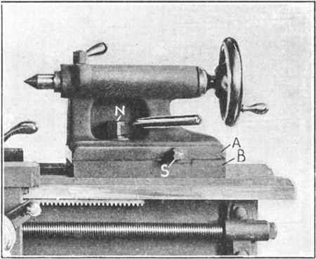
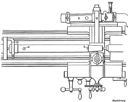
Fig. 3. Detail View of Lathe Tailstock
For example, the taper
roller B has a taper of
1 inch per foot, but the
center, in this case, would
be offset less than one-half
the taper per foot,
because the total length
is only 9 inches. For
lengths longer or shorter
than twelve inches, the
taper per inch should be
found first; this is then
multiplied by the total length of the work (not the length of the
taper) which gives the taper for that length, and one-half this
taper is the amount to set over the center. For example, the
taper per inch of part B equals 1 inch divided by 12 = 1/12 inch.
The total length of 9 inches multiplied by 1/12 inch =
3/4 inch, and
1/2 of 3/4 =
3/8, which is the distance that the tailstock center should
be offset. In this example if the taper per foot were not known,
and only the diameters of the large and small ends of the tapered
part were given, the difference between these diameters should
first be found (21/2 - 2 = 1/2);
this difference should then be divided
by the length of the taper (1/2 ÷ 6 = 1/12 inch) to obtain the taper
per inch. The taper per inch times the total length represents
what the taper would be if it extended throughout the entire
length, and one-half of this equals the offset, which is 3/8 inch.
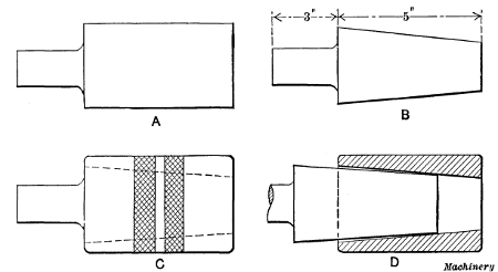
Fig. 4. Taper Plug and Gage
Example of Taper Turning.—As a practical example of taper
turning let us assume that the piece A, Fig. 4, which has been
centered and rough-turned as shown, is to be made into a taper
plug, as indicated at B, to fit a ring gage as at C. If the required
taper is 11/2 inch per foot and the total length is 8 inches,
the tailstock center would be offset 1/2 inch.
To adjust the tailstock, the nuts N (Fig. 3) are first loosened
and then the upper part A is shifted sidewise by turning screw S.
Scales are provided on some tailstocks for measuring the amount
of this adjustment; if there is no scale, draw a line across the
movable and stationary parts A and B, when the tailstock is
set for straight turning. The movement of the upper line in
relation to the lower will then show the offset, which can be
measured with a scale.
When the adjustment has been made, nuts N are tightened
and the part to be turned, with a dog attached, is placed between
the centers the same as for straight turning. The taper
end is then reduced by turning, but before it is near the finished
size, the work is removed and the taper tested by inserting it
in the gage. If it is much out, this can be felt, as the end that
is too small can be shaken in the hole. Suppose the plug did
not taper enough and only the small end came into contact with
the gage, as shown somewhat exaggerated at D; in that case the
center would be shifted a little more towards the front, whereas if the
taper were too steep, the adjustment would, of course, be in the
opposite direction. A light cut would then be taken, to be followed by
another test. If the plug should fit the gage so well that there was no
perceptible shake, it could be tested more closely as follows: Draw
three or four chalk lines along the tapering surface, place the work in
the gage and turn it a few times. The chalk marks will then show whether
the taper of the plug corresponds to that of the gage; for example, if
the taper is too great, the marks will be rubbed out on the large end,
but if the taper is correct, the lines throughout their length will be
partially erased.
Another and more accurate method of testing tapers is to
apply a thin coat of Prussian-blue to one-half of the tapering
surface, in a lengthwise direction. The work is then inserted in
the hole or gage and turned to mark the bearing. If the taper
is correct, the bearing marks will be evenly distributed, whereas
if the taper is incorrect, they will appear at one end. Tapering
pieces that have to be driven tightly into a hole, such as a piston-rod,
can be tested by the location of the bearing marks produced
by actual contact.
After the taper is found to be correct, the plug is reduced in
size until it just enters the gage as at C. The final cut should leave it slightly above the required size, so that a smooth surface can
be obtained by filing. It should be mentioned that on work of this
kind, especially if great accuracy is required, the final finish is
often obtained by grinding in a regular grinding machine, instead of by
filing. When this method is employed, a lathe is used merely to
rough-turn the part close to size.
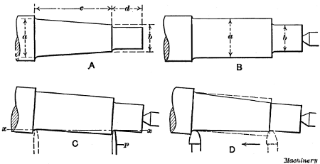
Fig. 5. Setting Work for Taper Turning by use of Caliper Gage
When the amount that the tailstock center should be offset
is determined by calculating, as in the foregoing example, it is
usually necessary to make slight changes afterward, and the
work should be tested before it is too near the finished size so
that in case one or more trial cuts are necessary, there will be
material enough to permit this. When there are a number of
tapered pieces to be turned to the same taper, the adjustment
of the tailstock center will have to be changed unless the total
length of each piece and the depth of the center holes are the
same in each case.
Fig. 6. Side View showing Relative Positions of Gage and Work
Setting the Tailstock Center with a Caliper Tool.—Another
method of setting the tailstock center for taper turning is illustrated
in Fig. 5. The end of an engine piston-rod is to be made
tapering as at A and to dimensions a, b, c and d. It is first
turned with the centers in line as at B. The end d is reduced to
diameter b up to the beginning of the taper and it is then turned
to diameter a as far as the taper part c extends. The tailstock
center is next set over by guess and a caliper tool is clamped in
the toolpost. This tool, a side view of which is shown in Fig. 6, has a pointer p that is free to swing about pivot r, which should
be set to about the same height as the center of the work. The
tailstock center is adjusted until this pointer just touches the
work when in the positions shown by the full and dotted lines
at C, Fig. 5; that is, until the pointer makes contact at the beginning
and end of the taper part. The travel of the carriage
will then be parallel to a line x—x, representing the taper; consequently,
if a tool is started at the small end, as shown by the
dotted lines at D, with the nose just grazing the work, it will
also just graze it when fed to the extreme left as shown. Of
course, if the taper were at all steep, more than one cut would
be taken.
Fig. 7. Obtaining Tailstock Center Adjustment by use of Square
If these various operations are carefully performed, a fairly
accurate taper can be produced. The straight end d is reduced to
size after the tail-center is set back to the central position. Some
mechanics turn notches or grooves at the beginning and end of the
tapering part, having diameters equal to the largest and smallest part
of the taper; the work is then set by these grooves with a caliper tool.
The advantage of the first method is that most of the metal is removed
while the centers are in alignment.
Setting the Tailstock Center with a Square.—Still another
method of adjusting the tailstock for taper turning, which is
very simple and eliminates all figuring, is as follows: The part
to be made tapering is first turned cylindrical or straight for
3 or 4 inches of its length, after the ends have been properly
centered and faced square. The work is then removed and the
tailstock is shifted along the bed until the distance a—b between
the extreme points of the centers is exactly 1 foot. The center
is next offset a distance b—c equal to one-half the required
taper per foot, after which a parallel strip D, having true sides,
is clamped in the toolpost. Part D is then set at right angles
to a line passing from one center point to the other. This can
be done conveniently by holding a 1-foot square (preferably with
a sliding head) against one side of D and adjusting the latter in
the toolpost until edge E of the square blade is exactly in line
with both center points. After part D is set, it should be
clamped carefully to prevent changing the position. The angle
between the side of D and an imaginary line which is perpendicular
to axis a—b is now equal to one-half the angle of the
required taper.
Fig. 8. Second Step in Adjusting Tailstock Center by use of Square
The axis of the part to be turned should be set parallel with
line E, which can be done by setting the cylindrical surface
which was previously finished, at right angles to the side of D.
In order to do this the work is first placed between centers, the
tailstock being shifted along the bed if necessary; the tail-center
is then adjusted laterally until the finished cylindrical
surface is square with the side of D. A small try-square can be
used for testing
the position of the
work, as indicated
in Fig. 8. If the
length of the work
is less than 1 foot,
it will be necessary
to move the
center toward the
rear of the machine,
and if the
length is greater
than 1 foot, the
adjustment is, of
course, in the opposite
direction.
The Taper Attachment.—Turning
tapers by setting over the tailstock center has some objectionable
features. When the lathe centers are not in alignment, as when set for
taper turning, they bear unevenly in the work centers because the axis
of the work is at an angle with them; this causes the work centers to
wear unevenly and results in inaccuracy. Furthermore, the adjustment of
the tailstock center must be changed when turning duplicate tapers,
unless the length of each piece and the depth of the center holes are
the same. To overcome these objections, many modern lathes are equipped
with a special device for turning tapers, known as a taper attachment,
which permits the lathe centers to be kept in alignment, as for
cylindrical turning, and enables more accurate work to be done.
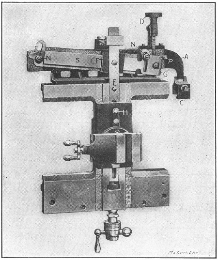
Fig. 9. A Lathe Taper Attachment
Taper attachments, like lathes, vary some in their construction,
but all operate on the same principle. An improved form
of taper attachment is illustrated in Figs. 9 and 10. Fig. 9
shows a plan view of a lathe carriage with an attachment
fitted to it, and Fig. 10 a sectional view. This attachment has
an arm A on which is mounted a slide S that can be turned
about a central pivot by adjusting screw D. The arm A is
supported by, and is free to slide on, a bracket B (see also sectional
view) that is fastened to the carriage, and on one end of
the arm there is a clamp C that is attached to the lathe bed
when turning tapers. On the slide S there is a shoe F that is
connected to bar E which passes beneath the toolslide. The
rear end of the cross-feed screw is connected to this bar, and
the latter is clamped to the toolslide when the attachment is
in use.
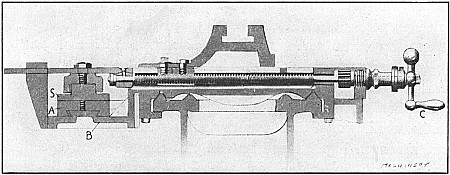
Fig. 10. Sectional View of Taper Attachment
When a taper is to be turned, the carriage is moved opposite
the taper part and clamp C is fastened to the bed; this holds
arm A and slide S stationary so that the carriage, with bracket
B and shoe F, can be moved with relation to the slide. If this
slide S is set at an angle, as shown, the shoe as it moves along
causes the toolslide and tool to move in or out, but if the slide is set
parallel to the carriage travel, the toolslide remains stationary. Now
if the tool, as it feeds lengthwise of the work, is also gradually moved
crosswise, it will turn a taper, and as this crosswise movement is
caused by the angularity of slide S,
different tapers are obtained by setting the slide to different
positions.
By means of a graduated scale G at the end of slide S, the
taper that will be obtained for any angular position of the slide
is shown. On some attachments there are two sets of graduations,
one giving the taper in inches per foot and the other in
degrees. While tapers are ordinarily given in inches per foot
on drawings, sometimes the taper is given in degrees instead.
The attachment is set for turning tapers by adjusting slide S
until pointer p is opposite the division or fractional part of a
division representing the taper. The whole divisions on the
scale represent taper in inches per foot, and by means of the
sub-divisions, the slide can be set for turning fractional parts of
an inch per foot. When slide S is properly set, it is clamped to
arm A by the nuts N. Bar E is also clamped to the toolslide by
bolt H, as previously stated. The attachment is disconnected
for straight turning by simply loosening clamp C and the bolt H.
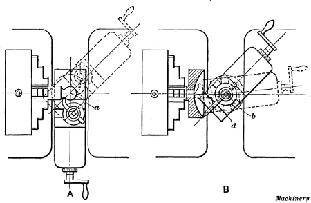
Fig. 11. Lathe with Taper Attachment arranged for Boring Taper Hole in Engine Piston
Application of Taper Attachment.—Practical examples of
lathe work, which illustrate the use of the taper attachment,
are shown in Figs. 11 and 12. Fig. 11 shows how a taper hole
is bored in an engine piston-head, preparatory to reaming.
The casting must be held either in a chuck C or on a faceplate
if too large for the chuck. The side of the casting (after it has
been “chucked”) should run true, and also the circumference,
unless the cored hole for the rod is considerably out of center,
in which case the work should be shifted to divide the error.
The side of the casting for a short space around the hole is faced
true with a round nose turning tool, after which the rough-cored
hole is bored with an ordinary boring tool t, and then it is
finished with a reamer to exactly the right size and taper.
Fig. 12. Taper Attachment Set for Turning Taper End of Piston-rod
This particular taper attachment is set to whatever taper is
given on the drawing, by loosening nuts N and turning slide S
until pointer P is opposite that division on the scale which represents
the taper. The attachment is then ready, after bolt H
and nuts N are tightened, and clamp C is fastened to the
lathe bed. The hole is bored just as though it were straight, and as the
carriage advances, the tool is gradually moved inward by the
attachment. If the lathe did not have a taper attachment, the taper hole
could be bored by using the compound rest.
The hole should be bored slightly less than the finish size to allow
for reaming. When a reamer is used in the lathe, the outer end is
supported by the tailstock center and should have a deep center-hole.
The lathe is run very slowly for reaming and the reamer is fed into the
work by feeding out the tailstock spindle. The reamer can be kept from
revolving, either by attaching a heavy dog to the end or, if the end is
squared, by the use of a wrench long enough to rest against the lathe
carriage. A common method is to clamp a dog to the reamer shank, and
then place the tool-rest beneath it to prevent rotation. If the shank of
a tool is clamped to the toolpost so that the dog rests against it, the
reamer will be prevented from slipping off the center as it tends to
do; with this arrangement, the carriage is gradually moved along as the
tailstock spindle is fed outward. Some reamers are provided with
stop-collars which come against the finished side of the casting when
the hole has been reamed to size.
After the reaming operation, the casting is removed from the
chuck and a taper mandrel is driven into the hole for turning
the outside of the piston. This mandrel should run true on its
centers, as otherwise the outside surface of the piston will not
be true with the bored hole. The driving dog, especially for
large work of this kind, should be heavy and stiff, because light
flexible clamps or dogs vibrate and frequently cause chattering.
For such heavy work it is also preferable to drive at two points
on opposite sides of the faceplate, but the driving pins should
be carefully adjusted to secure a uniform bearing on both sides.
The foregoing method of machining a piston is one that
would ordinarily be followed when using a standard engine
lathe, and it would, perhaps, be as economical as any if only one
piston were being made; but where such work is done in large
quantities, time could be saved by proceeding in a different
way. For example, the boring and reaming operation could be
performed much faster in a turret lathe, which is a type designed
for just such work, but a turret lathe cannot be used for
as great a variety of turning operations as a lathe of the regular
type. There are also many other classes of work that can be
turned more quickly in special types of machines, but as more
or less time is required for arranging these special machines and
often special tools have to be made, the ordinary lathe is frequently
indispensable when only a few parts are needed; in
addition, it is better adapted to some turning operations than
any other machine.
Fig. 12 illustrates how a taper attachment would be used for
turning the taper fitting for the crosshead end of an engine
piston-rod. Even though this taper corresponds to the taper of
the hole in the piston, slide S would have to be reset to the
corresponding division on the opposite side of the central zero mark,
because the taper of the hole decreased in size during the boring
operation, whereas the rod is smallest at the beginning of the cut, so
that the tool must move outward rather than inward as it advances. The
taper part is turned practically the same as a cylindrical part; that
is, the power feed is used and, as the carriage moves along the bed, the
tool is gradually moved outward by the taper attachment.
If the rod is being fitted directly to the crosshead (as is usually
the case), the approximate size of the small end of the taper could be
determined by calipering, the calipers being set to the size of the hole
at a distance from the shoulder or face side of the crosshead, equal to
the length of the taper fitting on the rod. If the crosshead were bored
originally to fit a standard plug gage, the taper on the rod could be
turned with reference to this gage, but, whatever the method, the taper
should be tested before turning too close to the finished size. The test
is made by removing the rod from the lathe and driving it tightly into
the crosshead. This shows how near the taper is to size, and when the
rod is driven out, the bearing marks show whether the taper is exactly
right or not. If the rod could be driven in until the shoulder is, say, 1/8 inch from the crosshead face, it
would then be near enough to finish to size by filing. When
filing, the lathe is run much faster than for turning, and most
of the filing should be done where the bearing marks are the
heaviest, to distribute the bearing throughout the length of the
taper. Care should be taken when driving the rod in or out,
to protect the center-holes in the ends by using a “soft” hammer
or holding a piece of soft metal against the driving end.
After the crosshead end is finished, the rod is reversed in the
lathe for turning the piston end. The dog is clamped to the
finished end, preferably over a piece of sheet copper to prevent
the surface from being marred. When turning this end, either
the piston reamer or the finished hole in the piston can be calipered.
The size and angle of the taper are tested by driving the
rod into the piston, and the end should be fitted so that by
driving tightly, the shoulder will just come up against the
finished face of the piston. When the taper is finished, the attachment
is disengaged and a finishing cut is taken over the
body of the rod, unless it is to be finished by grinding, which is
the modern and most economical method.
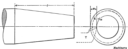
Fig. 13. Tool Point should be in same Horizontal Plane as Axis
of Work for Taper Turning
Height of Tool when Turning Tapers.—The
cutting edge of the tool, when turning tapers, should be at the same
height as the center or axis of the work, whether an attachment is used
or not. The importance of this will be apparent by referring to Fig. 13. To turn the taper shown, the tool T would be moved
back a distance x (assuming that an attachment is used) while
traversing the length l. As an illustration, if the tool could
be placed as high as point a, the setting of the attachment remaining
as before, the tool would again move back a distance x,
while traversing a distance l, but the large end would be under-sized
(as shown by the dotted line) if the diameters of the small
ends were the same in each case. Of course, if the tool point
were only slightly above or below the center, the resulting error
would also be small. The tool can easily be set central by comparing
the height of the cutting edge at the point of the tool with
one of the lathe centers before placing the work in the lathe.
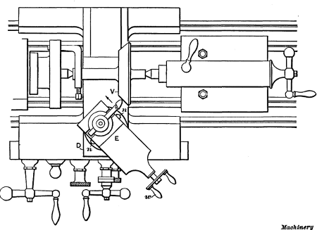
Fig. 14. Plan View showing Method of Turning a Taper with the Compound Rest
Taper Turning with the Compound Rest.—The amount of
taper that can be turned by setting over the tailstock center
and by the taper attachment is limited, as the centers can
only be offset a certain distance, and the slide S (Fig. 9) of the
attachment cannot be swiveled beyond a certain position. For
steep tapers, the compound rest E is swiveled to the required angle and used as indicated in Fig. 14, which shows a plan view
of a rest set for turning the valve V. This compound rest is an
upper slide mounted on the lower or main cross-slide D, and it
can be turned to any angular position so that the tool, which
ordinarily is moved either lengthwise or crosswise of the bed,
can be fed at an angle. The base of the compound rest is
graduated in degrees and the position of these graduations
shows to what angle the upper slide is set. Suppose the seat of
valve V is to be turned to an angle of 45 degrees with the axis
or center, as shown on the drawing at A, Fig. 15. To set the
compound rest, nuts n on either side, which hold it rigidly to
the lower slide, are first loosened and the slide is then turned
until the 45-degree graduation is exactly opposite the zero line;
the slide is then tightened in this position. A cut is next taken
across the valve by operating handle w and feeding the tool in
the direction of the arrow.
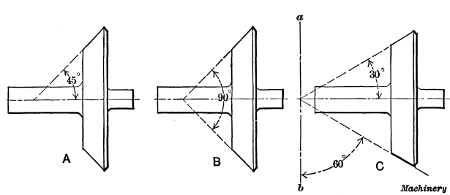
Fig. 15. Example of Taper Work Turned by using Compound Rest
In this particular instance the compound rest is set to the
same angle given on the drawing, but this is not always the
case. If the draftsman had given the included angle of 90
degrees, as shown at B, which would be another way of expressing
it, the setting of the compound rest would, of course, be the same as
before, or to 45 degrees, but the number of degrees marked on the
drawing does not correspond with the angle to which the rest must be
set. As another illustration, suppose the valve were to be turned to an
angle of 30 degrees with the axis as shown at C. In this case the compound rest would not
be set to 30 degrees but to 60 degrees, because in order to turn
the work to an angle of 30 degrees, the rest must be 60 degrees
from its zero position, as shown. From this it will be seen
that the number of degrees marked on the drawing does not
necessarily correspond to the angle to which the rest must be
set, as the graduations on the rest show the number of degrees
that it is moved from its zero position, which corresponds to
the line a—b. The angle to which the compound rest should be
set can be found, when the drawing is marked as at A or C,
by subtracting the angle given from 90 degrees. When the included
angle is given, as at B, subtract one-half the included
angle from 90 degrees to obtain the required setting. Of course,
when using a compound rest, the lathe centers are set in line as
for straight turning, as otherwise the angle will be incorrect.
Rules for Figuring Tapers
| Given |
To Find |
Rule |
| The taper per foot. |
The taper per inch. |
Divide the taper per foot by 12. |
| The taper per inch. |
The taper per foot. |
Multiply the taper per inch by 12. |
| End diameters and length of taper in inches. |
The taper per foot. |
Subtract small diameter from large; divide by length of taper, and multiply quotient by 12. |
| Large diameter and length of taper in inches and taper per foot. |
Diameter at small end in inches. |
Divide taper per foot by 12; multiply by length of taper, and subtract result from large diameter. |
| Small diameter and length of taper in inches, and taper per foot. |
Diameter at large end in inches. |
Divide taper per foot by 12; multiply by length of taper, and add result to small diameter. |
| The taper per foot and two diameters in inches. |
Distance between two given diameters in inches. |
Subtract small diameter from large; divide remainder by taper per foot, and multiply quotient by 12. |
| The taper per foot. |
Amount of taper in a certain length given in inches. |
Divide taper per foot by 12; multiply by given length of tapered part. |
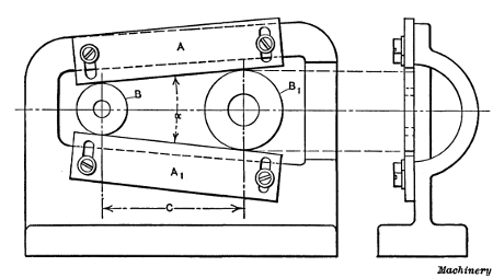
Fig. 16. Disk Gage for Accurate Measurement of Angles and Tapers
Accurate Measurement of Angles and Tapers.—When
great accuracy is required in the measurement of angles, or when
originating tapers, disks are commonly used. The principle of the disk
method of taper measurement is that if two disks of unequal diameters
are placed either in contact or a certain distance apart, lines tangent
to their peripheries will represent an angle or taper, the degree of
which depends upon the diameters of the two disks and the distance
between them. The gage shown in Fig. 16, which is a form commonly used for originating
tapers or measuring angles accurately, is set by means of disks.
This gage consists of two adjustable straight-edges A and A1,
which are in contact with disks B and B1. The angle α or the
taper between the straight-edges depends, of course, upon the
diameters of the disks and the center distance C, and as these
three dimensions can be measured accurately, it is possible to
set the gage to a given angle within very close limits. Moreover,
if a record of the three dimensions is kept, the exact setting
of the gage can be reproduced quickly at any time. The following
rules may be used for adjusting a gage of this type.
To Find Center Distance for a Given Taper.—When the
taper, in inches per foot, is given, to determine center distance
C. Rule: Divide the taper by 24 and find the angle corresponding
to the quotient in a table of tangents; then find the
sine corresponding to this angle and divide the difference between
the disk diameters by twice the sine.
Example: Gage is to be set to 3/4 inch per foot, and disk diameters
are 1.25 and 1.5 inch, respectively. Find the required
center distance for the disks.
The angle whose tangent is 0.03125 equals 1 degree 47.4 minutes;
To Find Center Distance for a Given Angle.—When straight-edges
must be set to a given angle α, to determine center distance
C between disks of known diameter. Rule: Find the sine
of half the angle α in a table of sines; divide the difference
between the disk diameters by double this sine.
Example: If an angle α of 20 degrees is required, and the
disks are 1 and 3 inches in diameter, respectively, find the required
center distance C.
To Find Angle for Given Taper per Foot.—When the taper
in inches per foot is known, and the corresponding angle α is
required. Rule: Divide the taper in inches per foot by 24;
find the angle corresponding to the quotient, in a table of tangents,
and double this angle.
Example: What angle α is equivalent to a taper of 11/2 inch
per foot?
The angle whose tangent is 0.0625 equals 3 degrees 35 minutes,
nearly; then, 3 deg. 35 min. × 2 = 7 deg. 10 min.
To Find Angle for Given Disk Dimensions.—When the
diameters of the large and small disks and the center distance
are given, to determine the angle α. Rule: Divide the
difference between the disk diameters by twice the center distance; find
the angle corresponding to the quotient, in a table of sines, and
double the angle.
Example: If the disk diameters are 1 and 1.5 inch, respectively,
and the center distance is 5 inches, find the included
angle α.
The angle whose sine is 0.05 equals 2 degrees 52 minutes; then,
2 deg. 52 min. × 2 = 5 deg. 44 min. = angle α.
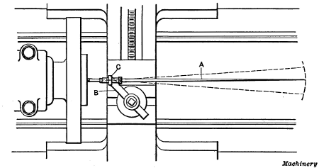
Fig. 17. Setting Center Mark in Line with Axis of Lathe Spindle
by use of Test Indicator
Use of the Center Indicator.—The center test indicator is
used for setting a center-punch mark, the position of which
corresponds with the center or axis of the hole to be bored, in
alignment with the axis of the lathe spindle. To illustrate, if
two holes are to be bored, say 5 inches apart, small punch
marks having that center-to-center distance would be laid out
as accurately as possible. One of these marks would then be
set central with the lathe spindle by using a center test indicator
as shown in Fig. 17. This indicator has a pointer A the
end of which is conical and enters the punch mark. The pointer
is held by shank B which is fastened in the toolpost. The
joint C by means of which the pointer is held to the shank is
universal; that is, it allows the pointer to move in any direction. Now
when the part being tested is rotated by running the lathe, if the
center-punch mark is not in line with the axes of the lathe spindle,
obviously the outer end of pointer A will
vibrate, and as joint C is quite close to the inner end, a very
slight error in the location of the center-punch mark will cause
a perceptible movement of the outer end, as indicated by the
dotted lines. When the work has been adjusted until the
pointer remains practically stationary, the punch mark is central,
and the hole is bored. The other center-punch mark is
then set in the same way for boring the second hole. The
accuracy of this method depends, of course, upon the location
of the center-punch marks. A still more accurate way of
setting parts for boring holes to a given center-to-center distance
is described in the following:
Locating Work by the Button Method.—Among the different
methods employed by machinists and toolmakers for accurately
locating work such as jigs, etc., on the faceplate of a lathe, the
one most commonly used is known as the button method.
This scheme is so named because cylindrical bushings or buttons
are attached to the work in positions corresponding to the
holes to be bored, after which they are used in locating the
work. These buttons, which are ordinarily about 1/2
inch in diameter, are ground and lapped to the same size and the ends
squared. The diameter should, preferably, be such that the radius can be
determined easily, and the hole through the center should be about 1/8 inch larger than the retaining screw, so that
the button can be shifted.
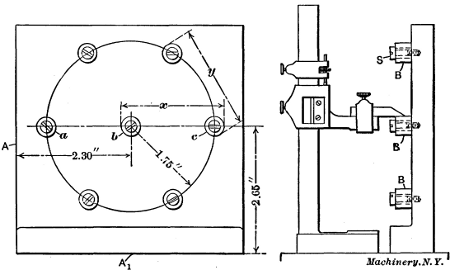
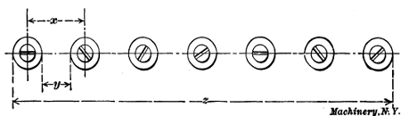
Fig. 18. Jig-plate with Buttons attached, ready for Boring
As an illustration of the practical application of the button
method, we shall consider, briefly, the way the holes would be
accurately machined in the jig-plate in Fig. 18. First the centers
of the seven holes should be laid off approximately correct
by the usual methods, after which small holes should be drilled
and tapped for the clamping screws S. After the buttons B
are clamped lightly in place, they are all set in correct relation
with each other and with the jig-plate. The proper location of
the buttons is very important as their positions largely determine
the accuracy of the work. A definite method of procedure
that would be applicable in all cases cannot, of course,
be given, as the nature of the work as well as the tools available
make it necessary to employ different methods.
In this particular case, the three buttons a, b and c should be
set first, beginning with the one in the center. As this central
hole must be 2.30 and 2.65 inches from the finished sides A and
A1, respectively, the work is first placed on an accurate surface-plate
as shown; by resting it first on one of these sides and then
on the other, and measuring with a vernier height gage, the
central button can be accurately set. The buttons a and c are
also set to the correct height from side A1 by using
the height gage, and in proper relation to the central button by using a
micrometer or a vernier caliper and measuring the over-all dimension x. When measuring in this way, the diameter of one
button would be deducted to obtain the correct center-to-center
distance. After buttons a, b and c are set equidistant from
side A1 and in proper relation to each other, the remaining
buttons should be set radially from the central button b and the
right distance apart. By having two micrometers or gages,
one set for the radial dimension x and the other for the chordal
distance y, the work may be done in a comparatively short
time.
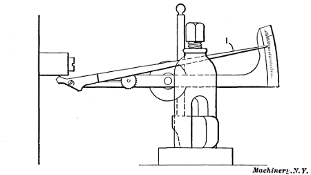
Fig. 19. Setting a Button True Preparatory to Boring, by use of
Test Indicator
After the buttons have been tightened, all measurements
should be carefully checked; the work is then mounted on the
faceplate of the lathe, and one of the buttons, say b, is set true
by the use of a test indicator as shown in Fig. 19. When the
end of this indicator (which is one of a number of types on
the market) is brought into contact with the revolving button,
the vibration of the pointer I shows how much the button runs
out of true. When the pointer remains practically stationary,
thus showing that the button runs true, the latter should be
removed. The hole is then drilled nearly to the required size,
after which it is bored to the finish diameter. In a similar[
manner the other buttons are indicated and the holes bored,
one at a time. It is evident that if each button is correctly
located and set perfectly true in the lathe, the various holes
will be located at the required center-to-center dimensions
within very close limits.
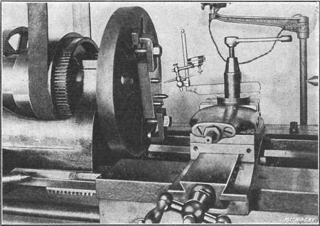
Fig. 20. Testing Concentricity of Button with Dial Gage
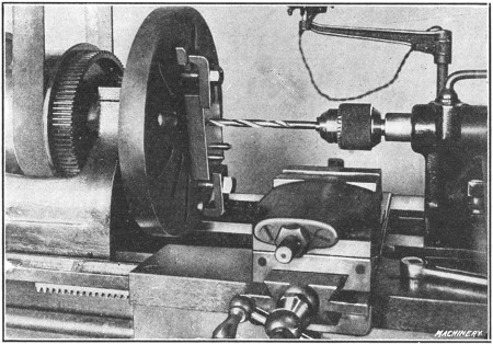
Fig. 21. Drilling a Bushing Hole
Fig. 20 shows how one of the buttons attached to a plate
in which three holes are to be bored is set true or concentric.
The particular indicator illustrated is of the dial type, any
error in the location of the button being shown by a hand over
a dial having graduations representing thousandths of an inch.
Fig. 21 shows how the hole is drilled after the button is removed.
It will be noted that the drill is held in a chuck, the
taper shank of which fits into the tailstock spindle, this being
the method of holding small drills. After drilling, the hole is
bored as shown in Fig. 22. The boring tool should have a
keen edge to avoid springing, and if the work when clamped in
position, throws the faceplate out of balance, it is advisable to
restore the balance, before boring, by the use of a counter-weight,
because the lathe can be rotated quite rapidly when
boring such a small hole.
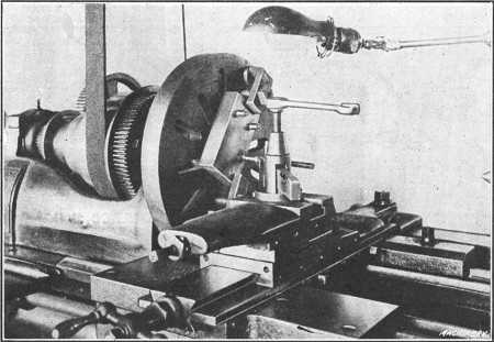
Fig. 22. Boring a Bushing Hole
Fig. 23. Example of Work illustrating Accumulation of Errors
When doing precision work of this kind, the degree of accuracy will
depend upon the instruments used, the judgment and skill of the workman
and the care exercised. A good general rule to follow when locating
bushings or buttons is to use the method which is the most direct and
which requires the least number of measurements. As an illustration of
how errors may accumulate, let us assume that seven holes are to be
bored in the jig-plate shown in Fig. 23, so that they are the
same distance from each other and in a straight line. The
buttons may be brought into alignment by the use of a straight-edge,
and to simplify matters, it will be taken for granted that
they have been ground and lapped to the same size. If the
diameter of the buttons is first determined by measuring with a
micrometer, and then this diameter is deducted from the center
distance x, the difference will be the distance y between adjacent
buttons. Now if a temporary gage is made to length y,
all the buttons can be set practically the same distance apart,
the error between any two adjacent ones being very slight.
If, however, the total length z over the end buttons is measured
by some accurate means, the chances are that this distance will
not equal six times dimension x plus the diameter of one button,
as it should, because even a very slight error in the gage for
distance y would gradually accumulate as each button was set. If a
micrometer were available that would span two of the buttons, the
measurements could be taken direct and greater accuracy would doubtless
be obtained. On work of this kind where there are a number of holes that
need to have accurate over-all dimensions, the long measurements should
first be taken when setting the buttons, providing, of course, there
are proper facilities for so doing, and then the short ones. For
example, the end buttons in this case should first be set, then the
central one and finally those for the sub-divisions.
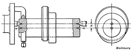
Fig. 24. Special Arbor for Turning Eccentrics
Eccentric Turning.—When one cylindrical surface must be
turned eccentric to another, as when turning the eccentric of
a steam engine, an arbor having two sets of centers is commonly
used, as shown in Fig. 24. The distance x between the
centers must equal one-half the total “throw” or stroke of the
eccentric. The hub of the eccentric is turned upon the centers
a—a, and the tongued eccentric surface, upon the offset centers,
as indicated by the illustration. Sometimes eccentrics are
turned while held upon special fixtures attached to the faceplate.
When making an eccentric arbor, the offset center in each end should
be laid out upon radial lines which can be drawn across the arbor ends
by means of a surface gage. Each center is then drilled and reamed to
the same radius x as near as
possible. The uniformity of the distance x at each end is then
tested by placing the mandrel upon the offset centers and rotating
it, by hand, with a dial indicator in contact at first one end
and then the other. The amount of offset can also be tested
either by measuring from the point of a tool held in the toolpost,
or by setting the tool to just graze the mandrel at extreme
inner and outer positions, and noting the movement of
the cross-slide by referring to the dial gage of the cross-feed
screw.
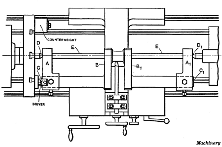
Fig. 25. Turning an Engine Crank-pin in an Ordinary Lathe
Turning a Crankshaft in a Lathe.—Another example of
eccentric turning is shown in Fig. 25. The operation is that of
turning the crank-pin of an engine crankshaft, in an ordinary
lathe. The main shaft is first rough-turned while the forging
revolves upon its centers C and C1 and the ends are turned to
fit closely the center-arms A and A1. After the sides B and
B1 of the crank webs have been rough-faced, the center-arms
are attached to the ends of the shaft as shown in the illustration.
These arms have centers at D and D1 (located at
the required crank radius) which should be aligned with the rough pin,
when attaching the arms, and it is advisable to insert braces E between
the arms and crank to take the thrust of the lathe centers.
With the forging supported in this way, the crank-pin and inner
sides of the webs are turned and faced, the work revolving
about the axis of the pin. The turning tools must extend beyond
the tool-holder far enough to allow the crank to clear as it
swings around. Owing to this overhang, the tool should be as
heavy as possible to make it rigid and it is necessary to take
comparatively light cuts and proceed rather cautiously. After
finishing the crank-pin and inside of the crank, the center-arms
are removed and the main body of the shaft and the sides B
and B1 are finished. This method of turning crankshafts is
often used in general repair shops, etc., especially where new
shafts do not have to be turned very often. It is slow and inefficient,
however, and where crankshafts are frequently turned,
special machines or attachments are used.
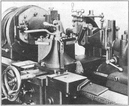
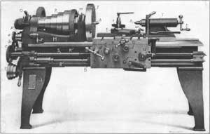
Fig. 26. LeBlond Lathe with Special Equipment for Crankshaft Turning
Special Crankshaft Lathe.—A lathe having special equipment for rough-turning gas engine crankshaft pins is shown in Fig. 26. This lathe is a heavy-duty type built by the R. K.
LeBlond Machine Tool Co. It is equipped with special adjustable
headstock and tailstock fixtures designed to take crankshafts
having strokes up to about 6 inches. The tools are held
in a three-tool turret type of toolpost and there are individual
cross-stops for each tool. This lathe also has a roller steadyrest
for supporting the crankshaft; automatic stops for the
longitudinal feed, and a pump for supplying cutting lubricant.
The headstock fixture is carried on a faceplate mounted on the
spindle and so arranged as to be adjustable for cranks of different
throw. When the proper adjustment for a given throw has
been made, the slide is secured by four T-bolts. A graduated
scale and adjusting screw permit of accurate adjustments.
The revolving fixture is accurately indexed for locating different
crank-pins in line with the lathe centers, by a hardened steel
plunger in the slide which engages with hardened bushings in
the fixture. The index is so divided that the fixture may be
rotated 120 or 180 degrees, making it adjustable for 2-, 4- and
6-throw cranks. After indexing, the fixture is clamped by two
T-bolts which engage a circular T-slot. The revolving fixture
is equipped with removable split bushings which can be replaced
to fit the line bearings of different sized crankshafts.
The work is driven by a V-shaped dovetail piece having a
hand-nut adjustment, which also centers the pin by the cheek
or web. The crank is held in position by a hinged clamp on
the fixture. The tailstock fixture is also adjustable and it is
mounted on a spindle which revolves in a bushing in the tailstock
barrel. The adjustment is obtained in the same manner
as on the headstock fixture, and removable split bushings as
well as a hinged clamp are also employed.
The method of chucking a four-throw crank is as follows: The two
fixtures are brought into alignment by two locking pins. One of these is
located in the head and enters a bushing in the large faceplate and the
other is in the tailstock and engages the tailstock fixture. The
crankshaft is delivered to the machine with the line bearings
rough-turned and it is clamped by the hinged clamp previously referred
to and centered by the V-shaped driver. The locking pins for both
fixtures are then withdrawn and the machine is ready to turn two of the
pins. After these have been machined, the fixtures are again aligned by
the locking pins, the two T-bolts of the headstock fixture and the
hinged clamp at the tailstock are released, the indexing plunger is
withdrawn and the headstock fixture and crank are turned 180 degrees or
until the index plunger drops into place. The crank is then clamped at
the tailstock end and the revolving fixture is secured by the two
T-bolts previously referred to. After the locking pins are withdrawn,
the lathe is ready to turn the two opposite pins.
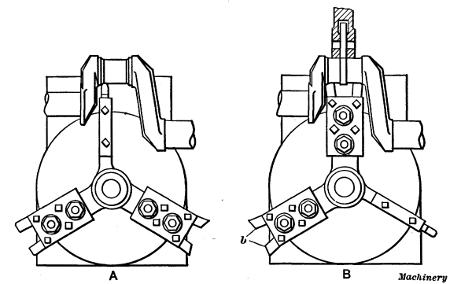
Fig. 27. Diagrams showing Arrangements of Tools on LeBlond Lathe
Operation of Special Crankshaft Lathe.—The total equipment
of this machine (see Fig. 27) is carried on a three-tool
turret tool-block. The method of turning a crankshaft is as
follows: A round-nosed turning tool is first fed into a cross stop
as illustrated in the plan view at A, which gives the proper
diameter. The feed is then engaged and the tool feeds across the pin
until the automatic stop lever engages the first stop, which throws out
the feed automatically. The carriage is then moved against a positive
stop by means of the handwheel. The roller back-rest is next adjusted
against the work by the cross-feed handwheel operating through a
telescopic screw, and the filleting tools are brought into position as
at B. These are
run in against a stop, removing the part left by the turning tool
and giving the pin the proper width and fillets of the correct
radius. If the crankshaft has straight webs which must be
finished, two tools seen at b are used for facing the webs to
the correct width. During these last two operations, the crank
is supported by the roller back-rest, thus eliminating any tendency
of the work to spring.
After one pin is finished in the manner described, the back-rest
is moved out of the way, the automatic stop lever raised,
the carriage shifted to the next pin, and the operation repeated.
The tools are held in position on the turret by studs,
and they can be moved and other tools quickly substituted for
pins of different widths. This machine is used for rough-turning
the pins close to the required size, the finishing operation
being done in a grinder. It should be mentioned, in
passing, that many crankshafts, especially the lighter designs
used in agricultural machinery, etc., are not turned at all but
are ground from the rough.
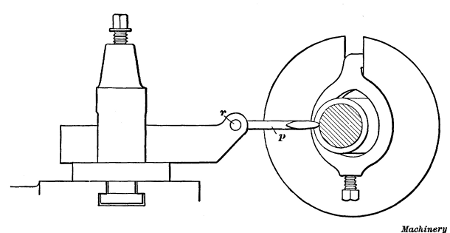
Fig. 28. (A) Spherical Turning with Compound Rest.
(B) Concave Turning
Spherical Turning.—Occasionally it may be necessary to
turn a spherical surface in the lathe. Sketch A, Fig. 28,
shows how a small ball-shaped end can be turned on a piece held in a
chuck. The lathe carriage is adjusted so that the pin around which the
compound rest swivels is directly under the center a. The bolts which
hold the swivel are slightly loosened to allow the top slide to be
turned, as indicated by the dotted lines; this causes the tool point to
move in an arc about center a, and
a spherical surface is turned. Light cuts must be taken as
otherwise it would be difficult to turn the slide around by
hand.
Sketch B illustrates how a concave surface can be turned.
The cross-slide is adjusted until swivel pin is in line with the
lathe centers, and the carriage is moved along the bed until
the horizontal distance between center b of the swivel, and the
face of the work, equals the desired radius of the concave surface.
The turning is then done by swinging the compound
rest as indicated by the dotted lines. The slide can be turned
more evenly by using the tailstock center to force it around.
A projecting bar is clamped across the end of the slide at d, to
act as a lever, and a centered bar is placed between this lever
and the tailstock center; then by screwing out the tailstock
spindle, the slide is turned about pivot b. The alignment between
the swivel pin and the lathe centers can be tested by
taking a trial cut; if the swivel pin is too far forward, the tool
will not touch the turned surface if moved past center c, and if
the pin is too far back, the tool will cut in on the rear side.
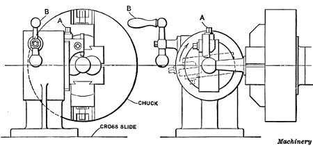
Fig. 29. Spherical Turning Attachment for Engine Lathe
Spherical Turning Attachments.—When spherical turning
must be done repeatedly, special attachments are sometimes
used. Fig. 29 shows an attachment applied to a lathe for turning
the spherical ends of ball-and-socket joints. The height or
radius of the cutting tool and, consequently, the diameter of
the turned ball, is regulated by adjusting screw A. The tool is
swung around in an arc, by turning handle B which revolves a
worm meshing with an enclosed worm-wheel. As will be seen,
the work is held in a special chuck, owing to its irregular
shape.
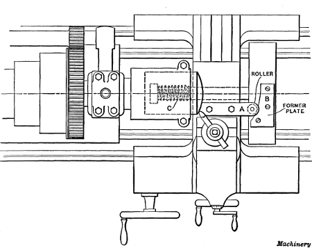
Fig. 30. Attachment for Turning Spherical End of Gasoline
Engine Piston
Another spherical turning attachment is shown in Fig. 30.
This is used for machining the ends of gasoline engine pistons.
The cross-slide has bolted to it a bar A carrying a roller which
is pressed against a forming plate B by a heavy spring C. The
forming plate B, which is attached to a cross-piece fastened to
the ways of the lathe bed, is curved to correspond with the radius
required on the piston end, and when the tool is fed laterally by moving
the cross-slide, it follows the curve of plate B. The piston is held in a special hollow chuck which locates
it in a central position and holds it rigidly.
In connection with lathe work, special attachments and tools
are often used, especially when considerable work of one class
must be turned; however, if a certain part is required in large
quantities, it is usually more economical to use some semi-automatic
or automatic turning machine, especially designed
for repetition work.
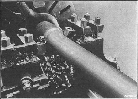
Fig. 31. Front and Rear Tools used for Roughing
Turning with Front and Rear Tools.—In ordinary engine
lathe practice, one tool is used at a time, but some lathes are
equipped with tool-holders at the front and rear of the carriage
so that two tools can be used simultaneously. Fig. 31 shows a
detail view of a lathe in which front and rear tools are being
used. These tools are of the inserted cutter type and the one
at the rear is inverted, as the rotary movement of the work is,
of course, upward on the rear side. This particular lathe was
designed for taking heavy roughing cuts and has considerable
driving power.
The part shown in this illustration is a chrome-nickel steel bar
which is being roughed out to form a milling machine spindle. It is
necessary to reduce the diameter of the bar from 57/16 inches to 33/4 inches for a length of 27 inches, because of a
collar on one end. This reduction is made in one passage of the
two tools, with a feed of 1/32 inch per revolution and a speed of
60 revolutions per minute. The use of two tools for such heavy
roughing cuts is desirable, especially when the parts are required
in large quantities, because the thrust of the cut on one
side, which tends to deflect the work, is counteracted by the
thrust on the opposite side.
Sometimes special tool-holders are made for the lathe, so
that more than one tool can be used for turning different surfaces
or diameters at the same time, the tools being set in the
proper relation to each other. The advantage of this method
has resulted in the design of a special lathe for multiple-tool
turning.
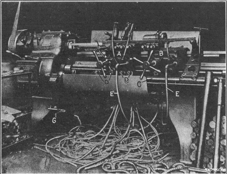
Fig. 32. Lo-swing Lathe for Multiple Turning
A Multiple-tool Lathe.—The lathe shown in Fig. 32 (which
is built by the Fitchburg Machine Works and is known as the
Lo-swing) is designed especially for turning shafts, pins and
forgings not exceeding 31/2 inches in diameter. It has two carriages A and B which, in conjunction with special tool-holders,
make it possible to turn several different diameters simultaneously.
At the front of this lathe there is an automatic stop-rod
C for disengaging the feed when the tools have turned a
surface to the required length. This stop-rod carries adjustable
stops D which are set to correspond with shoulders, etc.,
on the work. The rod itself is also adjustable axially, so that
the tools, which are usually arranged in groups of two or more
(depending upon the nature of the work), can be disengaged at
a point nearer or farther from the headstock as may be required,
owing to a variation in the depth of center holes. For example,
if it were necessary to feed a group of tools farther toward the
headstock after they had been automatically disengaged, the
entire rod with its stops would be adjusted the required amount
in that direction.
The gage G, which is attached to a swinging arm, is used to
set the stop bar with reference to a shoulder near the end of the work,
when it is necessary to finish other parts to a given distance from such
a shoulder or other surface. The use of this gage will be explained
more fully later. Cooling lubricant for the tools is supplied through
the tubes E. The lathe shown
in the illustration is arranged for turning Krupp steel bars.
A rough bar and also one that has been turned may be seen to
the right. The plain cylindrical bar is turned to five different
diameters, by groups of tools held on both carriages.
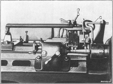
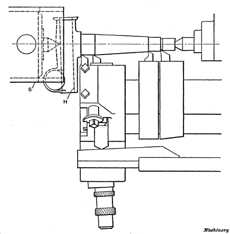
Fig. 33. Plan View showing Method of driving Steering Knuckle and Arrangement of Tools
Examples of Multiple Turning.—Figs. 33
and 34 show how a Lo-swing lathe is used for
turning the steering knuckle of an automobile. Four tools are used in
this case, three cylindrical surfaces and one tapering surface being
turned at the same time. For this job, the four tools are mounted on one
carriage. The taper part is turned by the second tool from the
headstock, which is caused to feed outward as the carriage advances by a
taper attachment. This tool is held in a special holder and bears
against a templet at the rear, which is tapered to correspond with the
taper to be turned. This templet is attached to a bar which, in turn, is
fastened to a stationary bracket seen to the extreme left in Fig. 33. This part is finished
in two operations, the tool setting being identical for each
operation, except for diameter adjustments. As the illustrations
show, three of the four tools employed are used for straight
turning on different diameters, while the fourth finishes the
taper.
Fig. 34. Plan View showing Method of driving Steering Knuckle and
Arrangement of Tools
These pieces, which are rough drop forgings, are first reduced
to the approximate size. When it becomes necessary to
grind the tools, they are reset and those parts which have been
roughed out are turned to the finished size. The average time
for the first operation, which includes starting, stopping, turning
and replacing the piece, is one minute, while for the second
operation with the finer feed, an average time of two minutes
is required. The work is driven by sleeve S, which fits over the
spindle and is held in position by the regular driver, as shown.
This sleeve is notched to fit the knuckle, so that the latter can
easily and quickly be replaced when finished.
One of the interesting features of this job lies in the method
of locating the shoulders on each knuckle, at the same distance
from the hole H which is drilled previously, and which receives
the bolt on which the knuckle swivels when assembled
in a car. As soon as the knuckle has been placed between the
centers, a close-fitting plug P (Fig. 33) is inserted in this hole
and the indicator arm with its attached gage or caliper G is
swung up to the position shown. The stop-rod on which the
stops have been previously set for the correct distance between
the shoulders is next adjusted axially until the gage G
just touches the plug P. The indicator is then swung out of the
way, and the piece turned. If the next knuckle were centered, say,
deeper than the previous one which would, of course, cause it to be
located nearer the headstock, obviously all the shoulders would be
located farther from the finished hole, provided the position of the
stops remained the same as before. In such a case their position would,
however, be changed by shifting the stop-rod until the gage G again touched the plug
thus locating all the stops with reference to the hole. As the
adjustment of the stop-rod changes the position of the taper
templet as well as the stops, it is evident that both the shoulders
and the taper are finished the same distance from the hole in
each case. The connection of the bracket (to which the templet
arm is attached) with the stop-rod is clearly shown in Fig. 33.
This bracket can either be locked to the ways or adjusted to
slide when the stop-rod is moved.
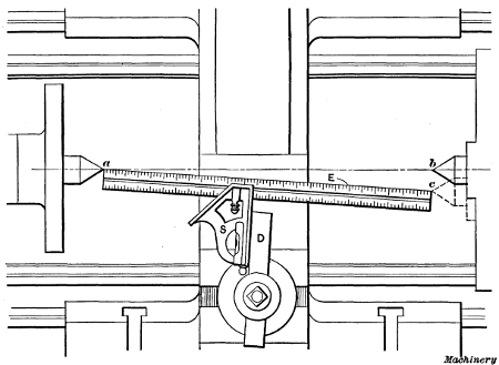
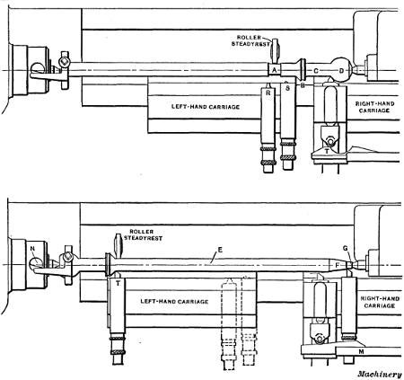
Fig. 35. First and Second Operations on Automobile Transmission
Shaft—Lo-swing Lathe
The part illustrated in Fig. 35 is an automobile transmission
shaft. In this particular case, cylindrical, tapering and spherical
surfaces are turned. The upper view shows, diagrammatically,
the arrangement of the tools and work for the first operation.
After the shaft is “spotted” at A for the steadyrest, the straight part C and the collar B are sized with tools S and R
which are mounted on the left-hand carriage. A concave groove
is then cut in collar B by tool R, after which spherical end D is
formed by a special attachment mounted on the right-hand carriage.
This attachment is the same, in principle, as the regular
taper-turning attachment, the substitution of a circular templet
T for the straight kind used on taper work being the only practical
difference.
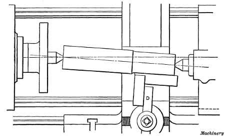
After the surfaces mentioned have been finished on a number
of pieces, the work is reversed and the tools changed as shown
by the lower view. The first step in the second operation is to
turn the body E of the shaft with the tool T on the left-hand
carriage. The taper F and the straight part G are then finished,
which completes the turning. It will be noted that in setting
up the machine for this second operation, it is arranged for
taper turning by simply replacing the circular templet with the
straight one shown. When this taper attachment is not in use,
the swiveling arm M, which is attached to a bracket, is swung
out of the way.
The method of driving this shaft is worthy of note. A dog
having two driving arms each of which bears against a pin N
that passes through a hole in the spindle is used. As the ends
of this pin, against which the dog bears, are beveled in opposite
directions, the pin turns in its hole when the dog makes contact
with it and automatically adjusts itself against the two driving
members of the dog. The advantage of driving by a two-tailed
dog, as most mechanics know, is in equalizing the tendency
to spring slender parts while they are being turned.
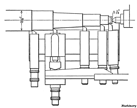
Fig. 36. Axle End turned in One Traverse of the Five Tools shown
In Fig. 36 another turning operation on a lathe of this type
is shown, the work in this case being a rear axle for a motor
truck. The turning of this part is a good example of that class
of work where the rapid removal of metal is the important
feature. As the engraving shows, the stock, prior to turning,
is 31/2 inches in diameter and it is reduced to a minimum diameter
of 11/16 inch. This
metal is turned off with one traverse of the carriage or by one passage
of the five tools, and the weight of the chips removed from each end of
the axle is approximately 12 pounds. The time required for the actual
turning is about 9 minutes, while the total time for the operation,
which includes placing the heavy piece in the machine, turning, and
removing the work from the lathe, is 12 minutes. The axle revolves,
while being turned, at 110 revolutions per minute and a feed equivalent
to 1 inch of tool travel to 60 revolutions of the work is used. It will
be noticed that the taper attachment is also employed on this part, the
taper being turned by the second tool from the left. As the axle is
equipped with roller bearings, it was found desirable to finish the
bearing part by a separate operation; therefore, in the operation shown
the axle is simply roughed down rather close to the finished dimensions,
leaving enough material for a light finishing cut.
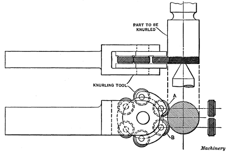
Fig. 37. Lathe Knurling Tool having Three Pairs of Knurls—Coarse,
Medium and Fine
Knurling in the Lathe.—Knurling is done either to provide
a rough surface which can be firmly gripped by the hand or for
producing an ornamental effect. The handles of gages and
other tools are often knurled, and the thumb-screws used on
instruments, etc., usually have knurled edges. A knurled surface
consists of a series of small ridges or diamond-shaped projections,
and is produced in the lathe by the use of a tool similar
to the one shown in Fig. 37, this being one of several different
designs in common use. The knurling is done by two knurls
A and B having teeth or ridges which incline to the right on one
knurl and to the left on the opposite knurl, as shown by the
end view. When these two knurls are pressed against the work
as the latter revolves, one knurl forms a series of left-hand
ridges and the other knurl right-hand ridges, which cross and
form the diamond-shaped knurling which is generally used.
If the surface to be knurled is wider than the knurls, the
power feed of the lathe should be engaged and the knurling tool
be traversed back and forth until the diamond-shaped projections
are well formed. To prevent forming a double set of
projections, feed the knurl in with considerable pressure at the
start, then partially relieve the pressure before engaging the
power feed. Use oil when knurling.
The knurls commonly used for lathe work have spiral teeth and
ordinarily there are three classes, known as coarse, medium and fine.
The medium pitch is generally used. The teeth of coarse knurls have a
spiral angle of 36 degrees and the pitch of the knurled cut (measured
parallel to the axis of the work) should be about 8 per inch. For medium
knurls, the spiral angle is 291/2 degrees and the pitch, measured as before, is 12
per inch. For fine knurls, the spiral angle is 253/4 degrees and
the pitch 20 per inch. The knurls should be about 3/4 inch in
diameter and 3/8 inch wide. When made to these dimensions,
coarse knurls have 34 teeth; medium, 50 teeth; and fine knurls,
80 teeth.
The particular tool illustrated in Fig. 37 has three pairs of
knurls of coarse, medium and fine pitch. These are mounted
in a revolving holder which not only serves to locate the required
set of knurls in the working position, but enables each
knurl to bear against the surface with equal pressure. Concave
knurls are sometimes used for knurling rounded edges on screw
heads, etc.
Relieving Attachment.—Some
lathes, particularly those used in toolrooms, are provided with
relieving attachments which are used for “backing off” the teeth of
milling cutters, taps, hobs, etc. If a milling cutter of special shape
is to be made, the cutter blank is first turned to the required form
with a special tool having a cutting edge that corresponds with the
shape or profile of the cutter to be made. The blank is then fluted or
gashed to form the teeth, after which the tops of the teeth are relieved
or backed off to provide clearance for the cutting edges. The forming
tool used for turning the blank is set to match the turned surface, and
the teeth are backed off as the result of a reciprocating action
imparted to the toolslide by the relieving attachment. The motion of the
toolslide is so adjusted that the tool will meet the front of each
tooth and the return movement begin promptly after the tool leaves the
back end of the tooth.
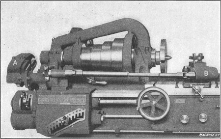
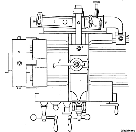
Fig. 38. Hendey Relieving Attachment applied to a Lathe
These attachments differ somewhat in their construction and
arrangement but the principle of their operation is similar.
Fig. 38 shows a Hendey relieving attachment applied to a lathe.
A bracket carrying the gearing A through which the attachment
is driven is mounted upon the main gear box of the lathe, and
the special slide B, which is used when relieving, is placed on
the cross-slide after removing the regular compound rest. The
gears at A are changed to suit the number of flutes or gashes in
the cutter, tap or whatever is to be relieved. If we assume that the
work is a formed milling cutter having nine teeth, then with this
particular attachment, a gear having 90 teeth would be placed on the
“stud” and a 40-tooth gear on the cam-shaft, the two gears being
connected by a 60-tooth intermediate gear. With this combination of
gearing, the toolslide would move in and out nine times for each
revolution of the work, so that the tool could back off the top of each
tooth. (The gearing to use for various numbers of flutes is shown by an
index plate on the attachment.) The amount of relief is varied to suit
the work being done, by means of a toothed coupling which makes it
possible to change the relative position between the eccentric which
actuates the toolslide and the cam lever, thereby lengthening or
shortening the reciprocating travel of the tool.
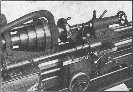
Fig. 39. Relieving a Formed Cutter
Application of Relieving Attachment.—Some typical examples
of the kind of work for which the relieving attachment
is used are shown in Figs. 39 to 42, inclusive. Fig. 39 shows
how a formed milling cutter is relieved. The toolslide is set at
right angles to the axis of the work, and the tool moves in as
each tooth passes, and out while crossing the spaces or flutes
between the teeth. As the result of this movement, the tops of
the teeth are backed off eccentrically but the form or shape is
the same from the front to the back of the tooth; hence, a
cutter that has been relieved in this way can be ground repeatedly
without changing the profile of the teeth, provided the
faces are ground so as to lie in a radial plane.
When relieving, the cutting speed should be much less than
when turning in order to give the toolslide time to operate
properly. A maximum of 180 teeth per minute is recommended,
and, if wide forming tools are used, it might be advisable
to reduce the speed so low that only 8 teeth per minute
would be relieved. It is also essential to use a tool having a keen
edge, and the toolslide should work freely but be closely adjusted
to the dovetail of the lower slide. Before beginning to
back off the teeth, it is a good plan to color the work either by
heating it or dipping into a strong solution of copper sulphate.
This will enable one to see plainly the cutting action of the
tool in order to stop relieving at the proper time.
Fig. 40. Relieving Side of Angular Milling Cutter
Fig. 40 shows a method of relieving the teeth
of an angular cutter. For an operation of this kind the toolslide is
swiveled around at right angles to the side that is to be relieved. By
the use of an additional universal joint and bearing to permit the
toolslide to be swung to a 90-degree angle, the teeth of counterbores,
etc., can be relieved on the ends. When the attachment is used for
relieving inside work, such as hollow mills and threading dies, the
eccentric which controls the travel of the toolslide is set so that the
relieving movement is away from the axis of the cutter instead of toward
it. This change is made by the toothed coupling previously referred to,
which connects the cam lever and oscillating shaft, the latter being
turned beyond the zero mark in a clockwise direction as far as is
necessary to obtain the desired amount of travel. For internal work it
is also necessary to change the position of the opposing spring of the
toolslide, so that it will press against the end of the slide and
prevent the tool from jumping into the work.
Fig. 41. Relieving a Right-hand Tap
Fig. 41 shows how a right-hand tap is
relieved. The ordinary practice is to first set the tool the same as for
cutting a thread. The motion of the toolslide is then adjusted so that
the tool on the forward stroke will meet the front of each tooth, and
start back as soon as the tool leaves the end of the land or top of the
tooth. Taps having a left-hand thread can be relieved by two different
methods. With the first method the cut starts at the cutting edge of
each tooth, and ends at the “heel,” the tool moving in toward the center
of the work. With the second method, the cut begins at the heel and
discontinues at the cutting edge, the tool being drawn away from the
work during the cut. When using the first method the tap must be placed
with the point toward the headstock, the shank end being supported by
the tailstock center. This is done by providing an extension or blank
end at the point of the tap long enough to hold the driving dog. With
the second method, the tap is held between centers the same as one
having a right-hand thread, but the travel of the toolslide is set the
same as for inside relief.
Fig. 42. Relieving a Hob having Spiral Flutes
Relieving Hobs or Taps Having Spiral Flutes.—With
this attachment, taps or hobs having “spiral” or helical flutes
can also be relieved. (A spiral flute is preferable to one that is
parallel to the axis, because with the former the tool has cutting
edges which are square with the teeth; this is of especial importance
when the lead of the hob or tap thread is considerable.)
When relieving work having spiral flutes (as illustrated in Fig.
42), the lead of the spiral and the gears necessary to drive the
attachment are first determined. After the attachment is
geared for the number of flutes and to compensate for the spiral,
the lead-screw is engaged and the backing-off operation is
performed the same as though the flutes were straight. The
carriage should not be disengaged from the lead-screw after
starting the cut, the tool being returned by reversing the lathe.
When gearing the attachment for relieving a tap or hob
having spiral flutes, the gears are not selected for the actual
number of flutes around the circumference but for a somewhat
larger number which depends upon the lead of the hob thread
and the lead of the spiral flutes. Let us assume that a hob
has 6 spiral flutes and that the attachment is geared for that
number. The result would be that as the tool advanced along
the thread, it would not keep “in step” with the teeth because
the faces of the teeth lie along a spiral (or helix which is the
correct name for this curve); in other words, the tool would
soon be moving in too late to begin cutting at the proper time,
and to compensate for this, the attachment is geared so that the
tool will make a greater number of strokes per revolution of the
work than the actual number of flutes around the circumference.
With this attachment, the two gears listed on the index plate for the
actual number of flutes are selected, and then two compensating gears
are added, thus forming a compound train of gearing. The ratio R of these compensating gears is determined
as follows:
in which
For example, if a hob has a pitch circumference of 3.25, a
single thread of 0.75 inch lead, and 6 spiral flutes, what compensating
gears would be required?
The lead L of the spiral flutes is first determined by dividing
the square of the circumference C of the hob at the pitch line by
the lead l of the hob thread. Thus lead L = C2 ÷ l, or, in this case,
L = 3.252 ÷ 0.75 = 14 inches, approximately. Then r = 14 ÷ 0.75 =
182/3. Inserting these values in the formula for ratio R,
Hence, the compensating gears will have 56 and 59 teeth, respectively,
the latter being the driver. As the gears for 6 flutes
listed on the regular index plate are, stud-gear 60 teeth, cam-shaft
gear 40 teeth, the entire train of gears would be as follows:
Gear on stud, 60; driven intermediate gear, 56; driving intermediate
gear, 59; cam-shaft gear, 40. It will be understood that
the position of the driving gears or the driven gears can be
transposed without affecting the ratio.
Classes of Fits Used in Machine Construction.—In
assembling machine parts it is necessary to have some members fit
together tightly, whereas other parts such as shafts, etc., must be free
to move or revolve with relation to each other. The accuracy required
for a fitting varies for different classes of work. A shaft that
revolves in its bearing must be slightly smaller than the bearing so
that there will be room for a film of lubricant. A crank-pin that must
be forced into the crank-disk is made a little larger in diameter than
the hole, to secure a tight fit. When a very accurate fitting between
two cylindrical parts that must be assembled without pressure is
required, the diameter of the inner member is made as close to the
diameter of the outer member as is possible. In ordinary machine
construction, five classes of fits are used, viz; running fit, push
fit, driving fit, forced fit and shrinkage fit. The running fit,
as the name implies, is employed when parts must rotate; the
push fit is not sufficiently free to rotate; the other classes referred
to are used for assembling parts that must be held in
fixed positions.
Forced Fits.—This is the term used when a pin, shaft or
other cylindrical part is forced into a hole of slightly smaller
diameter, by the use of a hydraulic press or other means. As a
rule, forced fits are restricted to parts of small and medium
size, while shrinkage fits have no such limitations and are especially
applicable when a maximum “grip” is desired, or when
(as in the construction of ordnance) accurate results as to the
intensity of stresses produced in the parts united are required.
The proper allowance for a forced fit depends upon the mass of
metal surrounding the hole, the size of the work, the kind and
quality of the material of which the parts are composed and the
smoothness and accuracy of the pin and bore. When a pin or
other part is pressed into a hole a second time, the allowance
for a given tonnage should be diminished somewhat because the
surface of the bore is smoother and the metal more compact.
The pressure required in assembling a forced fit will also vary
for cast hubs of the same size, if they are not uniform in hardness.
Then there is the personal factor which is much in evidence
in work of this kind; hence, data and formulas for forced
fit allowances must be general in their application.
Allowances for Different Classes of Fits
(Newall Engineering Co.)
| Class |
Tolerances in Standard Holes[1] |
| Nominal Diameters |
Up to 1/2" |
9/16" - 1" |
11/16" - 2" |
21/16" - 3" |
31/16" - 4" |
| A |
High Limit |
+ |
0.0002 |
+ |
0.0005 |
+ |
0.0007 |
+ |
0.0010 |
+ |
0.0010 |
| Low Limit |
- |
0.0002 |
- |
0.0002 |
- |
0.0002 |
- |
0.0005 |
- |
0.0005 |
| Tolerance |
|
0.0004 |
|
0.0007 |
|
0.0009 |
|
0.0015 |
|
0.0015 |
| B |
High Limit |
+ |
0.0005 |
+ |
0.0007 |
+ |
0.0010 |
+ |
0.0012 |
+ |
0.0015 |
| Low Limit |
- |
0.0005 |
- |
0.0005 |
- |
0.0005 |
- |
0.0007 |
- |
0.0007 |
| Tolerance |
|
0.0010 |
|
0.0012 |
|
0.0015 |
|
0.0019 |
|
0.0022 |
| Allowances for Forced Fits |
| F |
High Limit |
+ |
0.0010 |
+ |
0.0020 |
+ |
0.0040 |
+ |
0.0060 |
+ |
0.0080 |
| Low Limit |
+ |
0.0005 |
+ |
0.0015 |
+ |
0.0030 |
+ |
0.0045 |
+ |
0.0060 |
| Tolerance |
|
0.0005 |
|
0.0005 |
|
0.0010 |
|
0.0015 |
|
0.0020 |
| Allowances for Driving Fits |
| D |
High Limit |
+ |
0.0005 |
+ |
0.0010 |
+ |
0.0015 |
+ |
0.0025 |
+ |
0.0030 |
| Low Limit |
+ |
0.0002 |
+ |
0.0007 |
+ |
0.0010 |
+ |
0.0015 |
+ |
0.0020 |
| Tolerance |
|
0.0003 |
|
0.0003 |
|
0.0005 |
|
0.0010 |
|
0.0010 |
| Allowances for Push Fits |
| P |
High Limit |
- |
0.0002 |
- |
0.0002 |
- |
0.0002 |
- |
0.0005 |
- |
0.0005 |
| Low Limit |
- |
0.0007 |
- |
0.0007 |
- |
0.0007 |
- |
0.0010 |
- |
0.0010 |
| Tolerance |
|
0.0005 |
|
0.0005 |
|
0.0005 |
|
0.0005 |
|
0.0005 |
| Allowances for Running Fits[2] |
| X |
High Limit |
- |
0.0010 |
- |
0.0012 |
- |
0.0017 |
- |
0.0020 |
- |
0.0025 |
| Low Limit |
- |
0.0020 |
- |
0.0027 |
- |
0.0035 |
- |
0.0042 |
- |
0.0050 |
| Tolerance |
|
0.0010 |
|
0.0015 |
|
0.0018 |
|
0.0022 |
|
0.0025 |
| Y |
High Limit |
- |
0.0007 |
- |
0.0010 |
- |
0.0012 |
- |
0.0015 |
- |
0.0020 |
| Low Limit |
- |
0.0012 |
- |
0.0020 |
- |
0.0025 |
- |
0.0030 |
- |
0.0035 |
| Tolerance |
|
0.0005 |
|
0.0010 |
|
0.0013 |
|
0.0015 |
|
0.0015 |
| Z |
High Limit |
- |
0.0005 |
- |
0.0007 |
- |
0.0007 |
- |
0.0010 |
- |
0.0010 |
| Low Limit |
- |
0.0007 |
- |
0.0012 |
- |
0.0015 |
- |
0.0020 |
- |
0.0022 |
| Tolerance |
|
0.0002 |
|
0.0005 |
|
0.0008 |
|
0.0010 |
|
0.0012 |
Allowance for Forced Fits.—The
allowance per inch of diameter usually ranges from 0.001 inch to 0.0025
inch, 0.0015 being a fair average. Ordinarily, the allowance per inch
decreases as the diameter increases; thus the total allowance for a
diameter of 2 inches might be 0.004 inch, whereas for a diameter of 8
inches the total allowance might not be over 0.009 or 0.010 inch. In
some shops the allowance is made practically the same for all diameters,
the increased surface area of the larger sizes giving sufficient
increase in pressure. The parts to be assembled by forced fits are
usually made cylindrical, although sometimes they are slightly tapered.
The advantages of the taper form are that the possibility of abrasion of
the fitted surfaces is reduced; that less pressure is required in
assembling; and that the parts are more readily separated when renewal
is required. On the other hand, the taper fit is less reliable, because
if it loosens, the entire fit is free with but little axial movement.
Some lubricant, such as white lead and lard oil mixed to the consistency
of paint, should be applied to the pin and bore before assembling, to
reduce the tendency of abrasion.
Pressure for Forced Fits.—The pressure required for assembling
cylindrical parts depends not only upon the allowance for
the fit, but also upon the area of the fitted surfaces, the pressure
increasing in proportion to the distance that the inner member
is forced in. The approximate ultimate pressure in pounds can
be determined by the use of the following formula in conjunction
with the accompanying table of “Pressure Factors.”
Pressure Factors
| Diameter, Inches |
Pressure Factor |
Diameter, Inches |
Pressure Factor |
Diameter, Inches |
Pressure Factor |
Diameter, Inches |
Pressure Factor |
Diameter, Inches |
Pressure Factor |
| 1 |
500 |
31/2 |
132 |
6 |
75 |
9 |
48.7 |
14 |
30.5 |
| 11/4 |
395 |
33/4 |
123 |
61/4 |
72 |
91/2 |
46.0 |
141/2 |
29.4 |
| 11/2 |
325 |
4 |
115 |
61/2 |
69 |
10 |
43.5 |
15 |
28.3 |
| 13/4 |
276 |
41/4 |
108 |
63/4 |
66 |
101/2 |
41.3 |
151/2 |
27.4 |
| 2 |
240 |
41/2 |
101 |
7 |
64 |
11 |
39.3 |
16 |
26.5 |
| 21/4 |
212 |
43/4 |
96 |
71/4 |
61 |
111/2 |
37.5 |
161/2 |
25.6 |
| 21/2 |
189 |
5 |
91 |
71/2 |
59 |
12 |
35.9 |
17 |
24.8 |
| 23/4 |
171 |
51/4 |
86 |
73/4 |
57 |
121/2 |
34.4 |
171/2 |
24.1 |
| 3 |
156 |
51/2 |
82 |
8 |
55 |
13 |
33.0 |
18 |
23.4 |
| 31/4 |
143 |
53/4 |
78 |
81/2 |
52 |
131/2 |
31.7 |
.... |
.... |
Assuming that A = area of fitted surface; a = total allowance
in inches; P = ultimate pressure required, in tons; F =
pressure factor based upon assumption that the diameter of the hub is
twice the diameter of the bore, that the shaft is of machine steel, and
the hub of cast iron, then,
Example:—What will be the approximate pressure required
for forcing a 4-inch machine steel shaft having an allowance of
0.0085 inch into a cast-iron hub 6 inches long?
A = 4 × 3.1416 × 6 = 75.39 square inches;
F, for a diameter of 4 inches, = 115 (see table of “Pressure
Factors”). Then,
P = (75.39 × 0.0085 × 115)/2 = 37 tons, approximately.
Allowance for Given Pressure.—By transposing the preceding
formula, the approximate allowance for a required ultimate
tonnage can be determined. Thus, a = 2P ÷ AF. The average
ultimate pressure in tons commonly used ranges from 7 to 10
times the diameter in inches. Assuming that the diameter of a
machine steel shaft is 4 inches and an ultimate pressure of about
30 tons is desired for forcing it into a cast-iron hub having a
length of 51/2 inches, what should be the allowance?
A = 4 × 3.1416 × 51/2 = 69 square inches,
F, for a diameter of 4 inches, = 115. Then,
Shrinkage Fits.—When
heat is applied to a piece of metal, such as iron or steel, as is
commonly known, a certain amount of expansion takes place which
increases as the temperature is increased, and also varies somewhat with
different kinds of metal, copper and brass expanding more for a given
increase in temperature than iron and steel. When any part which has
been expanded by the application of heat is cooled, it contracts and
resumes its original size. This expansive property of metals has been
taken advantage of by mechanics in assembling various machine details. A
cylindrical part which is to be held in position by a shrinkage fit is
first turned a few thousandths of an inch larger than the hole; the
diameter of the latter is then increased by heating, and after the part
is inserted, the heated outer member is cooled, causing it to grip the
pin or shaft with tremendous pressure.
General practice seems to favor a smaller allowance for
shrinkage fits than for forced fits, although in many shops the
allowances are practically the same in each case, and for some
classes of work, shrinkage allowances exceed those for forced
fits. In any case, the shrinkage allowance varies to a great extent
with the form and construction of the part which has to be
shrunk into place. The thickness or amount of metal around
the hole is the most important factor. The way in which the
metal is distributed also has an influence on the results. Shrinkage
allowances for locomotive driving wheel tires adopted by the
American Railway Master Mechanics Association are as follows:
| Center diameter, inches | 38 | 44 | 50 |
56 | 62 | 66 |
| Allowance, inches | 0.040 | 0.047 | 0.053 |
0.060 | 0.066 | 0.070 |
Whether parts are to be assembled by forced or shrinkage
fits depends upon conditions. For example, to press a driving
wheel tire over its wheel center, without heating, would ordinarily
be a rather awkward and difficult job. On the other
hand, pins, etc., are easily and quickly forced into place with a
hydraulic press and there is the additional advantage of knowing
the exact pressure required in assembling, whereas there is
more or less uncertainty connected with a shrinkage fit, unless
the stresses are calculated. Tests to determine the difference
in the quality of shrinkage and forced fits showed that the resistance
of a shrinkage fit to slippage was, for an axial pull,
3.66 times greater than that of a forced fit, and in rotation or
torsion, 3.2 times greater. In each comparative test, the dimensions
and allowances were the same.
The most important point to consider when calculating
shrinkage fits is the stress in the hub at the bore, which depends
chiefly upon the shrinkage allowance. If the allowance
is excessive, the elastic limit of the material will be exceeded
and permanent set will occur, or, in extreme cases, the ultimate
strength of the metal will be exceeded and the hub will burst.
Return to Contents