|
Turning and Boring on a Lathe
Online Reprint Chapter 2
This a complete book, published in
1914, divided into chapters on how to use a metal lathe, covering all
turning and boring operations.
|
Return to Contents
Turning and Boring
by Franklin D. Jones
Published by Industrial Press 1914
A special treatise for machinists students in industrial and
engineering schools, and apprentices on turning and boring methods
including modern practice with engine lathes, vertical, and horizontal
boring machines.

Shop Amazon.com
|
CHAPTER II
LATHE TURNING TOOLS AND CUTTING SPEEDS
Notwithstanding the fact that a great variety of work can
be done in the lathe, the number of turning tools required is
comparatively small. Fig. 1 shows the forms of tools that are
used principally, and typical examples of the application of
these various tools are indicated in Fig. 2. The reference letters
used in these two illustrations correspond for tools of the same
type, and both views should be referred to in connection with
the following description.
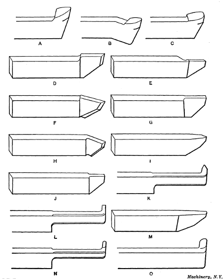
Fig. 1. Set of Lathe Turning Tools for General Work
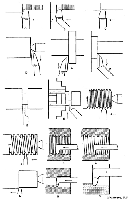
Fig. 2. Views illustrating Use of Various Types of Lathe Tools
Turning Tools for General Work.—The tool shown at A is
the form generally used for rough turning, that is for taking
deep cuts when considerable metal has to be removed. At B a
tool of the same type is shown, having a bent end which enables
it to be used close up to a shoulder or surface s that might come
in contact with the tool-rest if the straight form were employed.
Tool C, which has a straight cutting end, is used on certain
classes of work for taking light finishing cuts, with a coarse
feed. This type of tool has a flat or straight cutting edge at
the end, and will leave a smooth finish even though the feed is
coarse, provided the cutting edge is set parallel with the tool's
travel so as to avoid ridges. Broad-nosed tools and wide feeds
are better adapted for finishing cast iron than steel. When
turning steel, if the work is at all flexible, a broad tool tends to
gouge into it and for this reason round-nosed tools and finer
feeds are generally necessary. A little experience in turning
will teach more on this point than a whole chapter on the subject.
The side-tools shown at D and E are for facing the ends of
shafts, collars, etc. The first tool is known as a right side-tool
because it operates on the right end or side of a shaft or collar,
whereas the left side-tool E is used on the opposite side, as shown
in Fig. 2. Side-tools are also bent to the right
or left because the cutting edge of a straight tool cannot always be
located properly for facing certain surfaces. A bent right side-tool is
shown at F. A form of tool that is frequently used is shown at
G; this is known as a parting tool and is used for severing pieces
and for cutting grooves, squaring corners, etc. The same type
of tool having a bent end is shown at H (Fig. 2)
severing a piece held in the chuck. Work that is held between centers
should not be entirely severed with a parting tool unless a steadyrest
is placed between the tool and faceplate, as otherwise the tool may be
broken by the springing of the work just before the piece is cut in two.
It should be noted that the sides of this tool slope inward back of the
cutting edge to provide clearance when cutting in a narrow groove.
At I a thread tool is shown for cutting a U. S. standard thread.
This thread is the form most commonly used in this country at
the present time. A tool for cutting a square thread is shown
at J. This is shaped very much like a parting tool except that
the cutting end is inclined slightly to correspond with the helix
angle of the thread, as explained in Chapter IV, which contains
descriptions of different thread forms and methods of cutting
them. Internal thread tools are shown at K and L for cutting
U. S. standard and square threads in holes. It will be seen
that these tools are somewhat like boring tools excepting the
ends which are shaped to correspond with the thread which
they are intended to cut.
A tool for turning brass is shown at M. Brass tools intended
for general work are drawn out quite thin and they are given a
narrow rounded point. The top of the brass tool is usually
ground flat or without slope as otherwise it tends to gouge into
the work, especially if the latter is at all flexible. The end of a
brass tool is sometimes ground with a straight cutting edge for
turning large rigid work, such as brass pump linings, etc., so
that a coarse feed can be used without leaving a rough surface.
The tools at N and O are for boring or finishing drilled or cored
holes. Two sizes are shown, which are intended for small and
large holes, respectively.
The different tools referred to in the foregoing might be called
the standard types because they are the ones generally used,
and as Fig. 2 indicates, they make it possible to
turn an almost endless variety of forms. Occasionally some special form
of tool is needed for doing odd jobs, having, perhaps, an end bent
differently or a cutting edge shaped to some particular form. Tools of
the latter type, which are known as “form tools,” are sometimes used for
finishing surfaces that are either convex, concave, or irregular in
shape. The cutting edges of these tools are carefully filed or ground to
the required shape, and the form given the tool is reproduced in the
part turned. Ornamental or other irregular surfaces can be finished very
neatly by the use of such tools. It is very difficult, of course, to
turn convex or concave surfaces with a regular tool; in fact, it would
not be possible to form a true spherical surface, for instance, without
special equipment, because the tool could not be moved along a true
curve by simply using the longitudinal and cross feeds. Form tools
should be sharpened by grinding entirely on the top surface, as any
grinding on the end or flank would alter the shape of the tool.
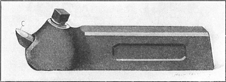
Fig. 3. Turning Tool with Inserted Cutter
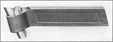
Fig. 4. Heavy Inserted-cutter Turning Tool
Tool-holders with Inserted Cutters.—All of the tools shown
in Fig. 1 are forged from the bar, and when the cutting ends
have been ground down considerably it is necessary to forge a
new end. To eliminate the expense of this continual dressing of
tools and also to effect a great reduction in the amount of tool
steel required, tool-holders having small inserted cutters are
used in many shops. A tool-holder of this type, for outside
turning, is shown in Fig. 3. The cutter C
is held in a fixed position by the set-screw shown, and it is sharpened,
principally, by grinding the end, except when it is desired to give the
top of the cutter a different slope from that due to its angular
position. Another inserted-cutter turning tool is shown in Fig. 4, which
is a heavy type intended for roughing. The cutter in this case
has teeth on the rear side engaging with corresponding teeth
cut in the clamping block which is tightened by a set-screw on
the side opposite that shown. With this arrangement, the cutter
can be adjusted upward as the top is ground away.
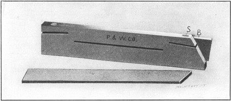
Fig. 5. Parting Tool with Inserted Blade
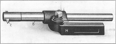
Fig. 6. Boring Tool with Inserted Cutter and Adjustable Bar
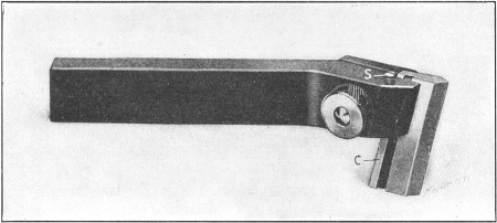
Fig. 7. Threading Tool
A parting tool of the inserted blade type is shown in Fig. 5.
The blade B is clamped by screw S and also by the spring of
the holder when the latter is clamped in the toolpost. The
blade can, of course, be moved outward when necessary. Fig. 6
shows a boring tool consisting of a holder H, a bar B that can
be clamped in any position, and an inserted cutter C. With this
type of boring tool, the bar can be extended beyond the holder
just far enough to reach through the hole to be bored, which
makes the tool very rigid. A thread tool of the holder type is
shown in Fig. 7. The angular edge of the cutter C
is accurately ground by the manufacturers, so that the tool is
sharpened by simply grinding it flat on the top. As the top is ground
away, the cutter is raised by turning screw S, which can also be used
for setting the tool to the proper height.
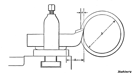
Fig. 8. To avoid springing, Overhang A of Tool should not be Excessive
The Position of Turning Tools.—The production of accurate
lathe work depends partly on the condition of the lathe used
and also on the care and judgment exercised by the man operating
it. Even though a lathe is properly adjusted and in good
condition otherwise, errors are often made which are due to
other causes which should be carefully avoided. If the turning
tool is clamped so that the cutting end extends too far from the
supporting block, the downward spring of the tool, owing to
the thrust of the cut, sometimes results in spoiled work, especially
when an attempt is made to turn close to the finished
size by taking a heavy roughing cut. Suppose the end of a
cylindrical part is first reduced for a short distance by taking
several trial cuts until the diameter d, Fig. 8, is slightly above
the finished size and the power feed is then engaged. When
the tool begins to take the full depth e of the cut, the point,
which ordinarily would be set a little above the center, tends to
spring downward into the work, and if there were considerable
springing action, the part would probably be turned below the
finished size, the increased reduction beginning at the point
where the full cut started.
This springing action, as far as the tool is concerned, can be practically eliminated by locating the tool so that the distance A between the tool-block and cutting end, or the “overhang,”
is as short as possible. Even though the tool has little overhang
it may tilt downward because the toolslide is loose on its ways,
and for this reason the slide should have a snug adjustment
that will permit an easy movement without unnecessary play.
The toolslides of all lathes are provided with gibs which can
be adjusted by screws to compensate for wear, or to secure a
more rigid bearing.
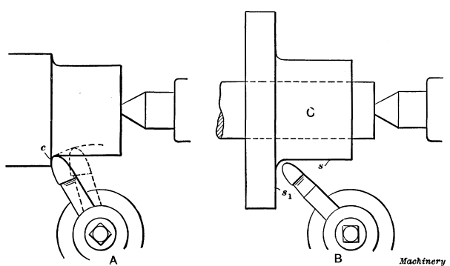
Fig. 9. (A) The Way in which Tool is sometimes displaced by Thrust of Cut,
when set at an Angle.
(B) Tool Set for Finishing both Cylindrical and
Radial Surfaces
When roughing cuts are to be taken, the tool should be located
so that any change in its position which might be caused by the
pressure of the cut will not spoil the work. This point is illustrated
at A in Fig. 9. Suppose the end of a rod has been reduced
by taking a number of trial cuts, until it is 1/32 inch above the
finished size. If the power feed is then engaged with the tool
clamped in an oblique position, as shown, when the full cut is
encountered at c, the tool, unless very tightly clamped, may be
shifted backward by the lateral thrust of the cut, as indicated by the
dotted lines. The point will then begin turning smaller than the
finished size and the work will be spoiled. To prevent any change of
position, it is good practice, especially when roughing, to clamp the
tool square with the surface being turned, or in other words, at right
angles to its direction of movement. Occasionally, however, there is a
decided advantage in having the tool set at an angle. For example, if it
is held about as shown at B, when turning the flange casting C, the surfaces s
and s1 can be finished without changing the tool's position.
Cylindrical and radial surfaces are often turned in this way
in order to avoid shifting the tool, especially when machining
parts in quantity.
Tool Grinding.—In the grinding of lathe tools there are
three things of importance to be considered: First, the cutting
edge of the tool (as viewed from the top) needs to be given a
certain shape; second, there must be a sufficient amount of
clearance for the cutting edge; and third, tools, with certain
exceptions, are ground with a backward slope or a side slope,
or with a combination of these two slopes on that part against
which the chip bears when the tool is in use.
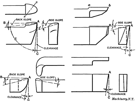
Fig. 10. Illustration showing the Meaning of Terms used
in Tool
Grinding as applied to Tools of Different Types
In Fig. 10 a few of the different types of tools which are used
in connection with lathe work are shown. This illustration also
indicates the meaning of the various terms used in tool grinding.
As shown, the clearance of the tool is represented by the
angle α, the back slope is represented by the angle β, and the
side slope by the angle γ. The angle δ for a tool without
side slope is known as the lip angle or the angle of keenness. When,
however, the tool has both back and side slopes, this lip angle would
more properly be the angle between the flank f and the
top of the tool, measured diagonally along a line z—z. It will
be seen that the lines A—B and A—C from which the angles
of clearance and back slope are measured are parallel with the
top and sides of the tool shank, respectively. For lathe tools,
however, these lines are not necessarily located in this way
when the tool is in use, as the height of the tool point with
relation to the work center determines the position of these
lines, so that the effective angles of back slope, clearance and
keenness are changed as the tool point is lowered or raised.
The way the position of the tool affects these angles will be
explained later.
While tools must, of necessity, be varied considerably in shape to
adapt them to various purposes, there are certain underlying principles
governing their shape which apply generally; so in what follows we shall
not attempt to explain in detail just what the form of each tool used
on the lathe should be, as it is more important to understand how the
cutting action of the tool and its efficiency is affected when it is
improperly ground.When the principle is understood, the grinding of
tools of various types and shapes is comparatively easy.
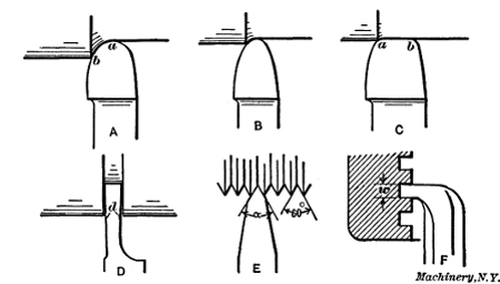
Fig. 11. Plan View of Lathe Turning and Threading Tools
Shape or Contour of Cutting Edge.—In the first place we
shall consider the shape or contour of the cutting edge of the
tool as viewed from the top, and then take up the question of
clearance and slope, the different elements being considered
separately to avoid confusion. The contour of the cutting edge
depends primarily upon the purpose for which the tool is intended.
For example, the tool A, in Fig. 11, where a plan view
of a number of different lathe tools is shown, has a very different
shape from that of, say, tool D, as the first tool is used for rough
turning, while tool D is intended for cutting grooves or severing
a turned part. Similarly, tool E is V-shaped because it is used
for cutting V-threads. Tools A, B and C, however, are regular
turning tools; that is, they are all intended for turning plain
cylindrical surfaces, but the contour of the cutting edges varies
considerably, as shown. In this case it is the characteristics of
the work and the cut that are the factors which determine the
shape. To illustrate, tool A is of a shape suitable for rough-turning
large and rigid work, while tool B is adapted for smaller
and more flexible parts. The first tool is well shaped for roughing
because experiments have shown that a cutting edge of a
large radius is capable of higher cutting speed than could be
used with a tool like B, which has a smaller point. This increase
in the cutting speed is due to the fact that the tool A
removes a thinner chip for a given feed than tool B; therefore,
the speed may be increased without injuring the cutting edge
to the same extent. If, however, tool A were to be used for
turning a long and flexible part, chattering might result; consequently,
a tool B having a point with a smaller radius would
be preferable, if not absolutely necessary.
The character of the work also affects the shape of tools.
The tool shown at C is used for taking light finishing cuts with
a wide feed. Obviously, if the straight or flat part of the cutting
edge is in line with the travel of the tool, the cut will be smooth
and free from ridges, even though the feed is coarse, and by
using a coarse feed the cut is taken in less time; but such a
tool cannot be used on work that is not rigid, as chattering
would result. Therefore, a smaller cutting point and a reduced
feed would have to be employed. Tools with broad flat cutting
edges and coarse feeds are often used for taking finishing cuts
in cast iron, as this metal offers less resistance to cutting than
steel, and is less conducive to chattering.
The shape of a tool (as viewed from the top) which is intended
for a more specific purpose than regular turning, can be largely
determined by simply considering the tool under working conditions.
This point may be illustrated by the parting tool D
which, as previously stated, is used for cutting grooves, squaring
corners, etc. Evidently this tool should be widest at the
cutting edge; that is, the sides d should have a slight amount
of clearance so that they will not bind as the tool is fed into a
groove. As the tool at E is for cutting a V-thread, the angle α
between its cutting edges must equal the angle between the
sides of a V-thread, or 60 degrees. The tool illustrated at F is
for cutting inside square threads. In this case the width w
should be made equal to one-half the pitch of the thread (or
slightly greater to provide clearance for the screw), and the
sides should be given a slight amount of side clearance, the
same as with the parting tool D. So we see that the outline of
the tool, as viewed from the top, must conform to and be governed
by its use.
Direction of Top Slope for Turning Tools.—Aside from the
question of the shape of the cutting edge as viewed from the
top, there remains to be determined the amount of clearance
that the tool shall have, and also the slope (and its direction) of
the top of the tool. By the top is meant that surface against
which the chip bears while it is being severed. It may be stated,
in a general way, that the direction in which the top of the tool
should slope should be away from what is to be the working
part of the cutting edge. For example, the working edge of a
roughing tool A (Fig. 11), which is used for heavy cuts, would
be, practically speaking, between points a and b, or, in other
words, most of the work would be done by this part of the cutting
edge; therefore the top should slope back from this part
of the edge. Obviously, a tool ground in this way will have
both a back and a side slope.
When most of the work is done on the point or nose of the
tool, as, for example, with the lathe finishing tool C which takes
light cuts, the slope should be straight back from the point or
cutting edge a—b. As the side tool shown in Fig. 10 does its
cutting along the edge a—b, the top is given a slope back from
this edge as shown in the end view. This point should be
remembered, for when the top slopes in the right direction, less
power is required for cutting. Tools for certain classes of work,
such as thread tools, or those for turning brass or chilled iron,
are ground flat on top, that is, without back or side slope.
Clearance for the Cutting Edge.—In order that the cutting
edge may work without interference, it must have clearance;
that is, the flank f (Fig. 10) must be ground to a certain angle α
so that it will not rub against the work and prevent the cutting
edge from entering the metal. This clearance should be just
enough to permit the tool to cut freely. A clearance angle of
eight or ten degrees is about right for lathe turning tools.
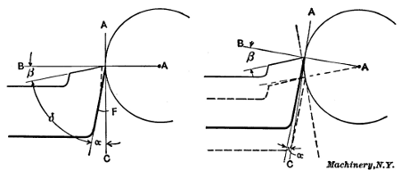
Fig. 12. Illustrations showing how Effective Angles of Slope
and
Clearance change as Tool is raised or lowered
The back slope of a tool is measured from a line A—B which is
parallel to the shank, and the clearance angle, from a line A—C
at right angles to line A—B. These lines do not, however, always
occupy this position with relation to the tool shank when
the tool is in use. As shown to the left in Fig. 12, the base line A—B for a turning tool in use intersects with the point of the
tool and center of the work, while the line A—C remains at right
angles to the first. It will be seen, then, that by raising the
tool, as shown to the right, the effective clearance angle α will
be diminished, whereas lowering it, as shown by the dotted
lines, will have the opposite effect.
A turning tool for brass or other soft metal, particularly
where considerable hand manipulation is required, could advantageously
have a clearance of twelve or fourteen degrees,
as it would then be easier to feed the tool into the metal; but,
generally speaking, the clearance for turning tools should be
just enough to permit them to cut freely. Excessive clearance
weakens the cutting edge and may cause it to crumble under
the pressure of the cut.
Angle of Tool-point and Amount of Top Slope.—The lip
angle or the angle of keenness δ (Fig. 10) is another important
consideration in connection with tool grinding, for it is upon
this angle that the efficiency of the tool largely depends. By
referring to the illustration it will be seen that this angle is
governed by the clearance and the slope β, and as the clearance
remains practically the same, it is the slope which is varied to meet
different conditions. Now, the amount of slope a tool should have
depends on the work for which it is intended. If, for example, a turning
tool is to be used for roughing medium or soft steel, it should have a
back slope of about eight degrees and a side slope ranging from fourteen
to twenty degrees, while a tool for cutting very hard steel should
have a back slope of about five degrees and a side slope of nine
degrees.
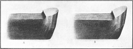
Fig. 13. (A) Blunt Tool for Turning Hard Steel.
(B) Tool-point
Ground to give Keenness
The reason for decreasing the slope and thus increasing the
lip angle for harder metals is to give the necessary increased
strength to the cutting edge to prevent it from crumbling under
the pressure of the cut. The tool illustrated at A, Fig. 13, is
much stronger than it would be if ground as shown at B, as
the former is more blunt. If a tool ground as at A, however,
were used for cutting very soft steel, there would be a greater
chip pressure on the top and, consequently, a greater resistance
to cutting, than if a keener tool had been employed; furthermore
the cutting speed would have to be lower, which is of
even greater importance than the chip pressure; therefore, the
lip angle, as a general rule, should be as small as possible without
weakening the tool so that it cannot do the required work.
In order to secure a strong and well-supported cutting edge,
tools used for turning very hard metal, such as chilled rolls,
etc., are ground with practically no slope and with very little
clearance. Brass tools, while given considerable clearance, as
previously stated, are ground flat on top or without slope; this
is not done, however, to give strength to the cutting edge, but
rather to prevent the tool from gouging into the work, which it
is likely to do if the part being turned is at all flexible and the
tool has top slope.
Experiments conducted by Mr. F. W. Taylor to determine the most
efficient form for lathe roughing tools showed that the nearer the lip
angle approached sixty-one degrees, the higher the cutting speed. This,
however, does not apply to tools for turning cast iron, as the latter
will work more efficiently with a lip angle of about sixty-eight
degrees. This is doubtless because the chip pressure, when turning cast
iron, comes closer to the cutting edge which should, therefore, be more
blunt to withstand the abrasive action and heat. Of course, the
foregoing remarks concerning lip angles apply more particularly to tools
used for roughing.
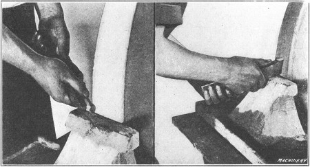
Fig. 14. Grinding the Top and Flank of a Turning Tool
Grinding a Lathe Tool.—The way a turning tool is held
while the top surface is being ground is shown to the left in
Fig. 14. By inclining the tool with the wheel face, it will be
seen that both the back and side slopes may be ground at the
same time. When grinding the flank of the tool it should be
held on the tool-rest of the emery wheel or grindstone, as shown
by the view to the right. In order to form a curved cutting
edge, the tool is turned about the face of the stone while it is
being ground. This rotary movement can be effected by supporting
the inner end of the tool with one hand while the shank
is moved to and fro with the other.
Often a tool which has been ground properly in the first place is
greatly misshapen after it has been sharpened a few times. This is
usually the result of attempts on the part of the workman to re-sharpen
it hurriedly; for example, it is easier to secure a sharp edge on the turning tool shown to the left in Fig. 12, by
grinding the flank as indicated by the dotted line, than by
grinding the entire flank. The clearance is, however, reduced
and the lip angle changed.
There is great danger when grinding a tool of burning it or
drawing the temper from the fine cutting edge, and, aside from
the actual shape of the cutting end, this is the most important
point in connection with tool grinding. If a tool is pressed
hard against an emery or other abrasive wheel, even though the
latter has a copious supply of water, the temper will sometimes
be drawn. When grinding a flat surface, to avoid burning, the
tool should frequently be withdrawn from the stone so that the
cooling water (a copious supply of which should be provided)
can reach the surface being ground. A moderate pressure
should also be applied, as it is better to spend an extra minute
or two in grinding than to ruin the tool by burning, in an attempt
to sharpen it quickly. Of course, what has been said
about burning applies more particularly to carbon steel, but
even self-hardening steels are not improved by being over-heated
at the stone. In some shops, tools are ground to the
theoretically correct shape in special machines instead of by
hand. The sharpened tools are then kept in the tool-room and
are given out as they are needed.
Cutting Speeds and Feeds.—The term cutting speed as applied
to turning operations is the speed in feet per minute of
the surface being turned, or, practically speaking, it is equivalent
to the length of a chip, in feet, which would be turned in
one minute. The term cutting speed should not be confused
with revolutions per minute, because the cutting speed depends
not only upon the speed of the work but also upon its diameter.
The feed of a tool is the amount it moves across the surface
being turned for each revolution; that is, when turning a cylindrical
piece, the feed is the amount that the tool moves sidewise
for each revolution of the work. Evidently the time required
for turning is governed largely by the cutting speed, the feed,
and the depth of the cut; therefore, these elements should be
carefully considered.
Cutting Speeds and Feeds for Turning Tools[1]
| Steel—Standard 7/8-inch Tool |
Cast Iron—Standard 7/8-inch Tool
|
| Depth of Cut in Inches |
Feed in Inches |
Speed in Feet per Minute for a Tool which is to last 11/2
Hour before Re-grinding |
Depth of Cut in Inches |
Feed in Inches |
Speed in Feet per Minute for a Tool which is to last 11/2
Hour before Re-grinding |
Soft
Steel |
Medium
Steel |
Hard
Steel |
Soft
Cast Iron |
Medium
Cast Iron |
Hard
Cast Iron |
| 3/32 |
1/64 |
476 |
|
238 |
|
108 |
|
3/32 |
1/16 |
122 |
|
61 |
.2 |
35 |
.7 |
| 1/32 |
325 |
|
162 |
|
73 |
.8 |
1/8 |
86 |
.4 |
43 |
.2 |
25 |
.2 |
| 1/16 |
222 |
|
111 |
|
50 |
.4 |
3/16 |
70 |
.1 |
35 |
.1 |
20 |
.5 |
| 3/32 |
177 |
|
88 |
.4 |
40 |
.2 |
1/8 |
1/32 |
156 |
|
77 |
.8 |
45 |
.4 |
| 1/8 |
1/64 |
420 |
|
210 |
|
95 |
.5 |
1/16 |
112 |
|
56 |
.2 |
32 |
.8 |
| 1/32 |
286 |
|
143 |
|
65 |
.0 |
1/8 |
79 |
.3 |
39 |
.7 |
23 |
.2 |
| 1/16 |
195 |
|
97 |
.6 |
44 |
.4 |
3/16 |
64 |
.3 |
32 |
.2 |
18 |
.8 |
| 1/8 |
133 |
|
66 |
.4 |
30 |
.2 |
3/16 |
1/32 |
137 |
|
68 |
.6 |
40 |
.1 |
| 3/16 |
1/64 |
352 |
|
176 |
|
80 |
.0 |
1/16 |
99 |
.4 |
49 |
.7 |
29 |
.0 |
| 1/32 |
240 |
|
120 |
|
54 |
.5 |
1/8 |
70 |
.1 |
35 |
.0 |
20 |
.5 |
| 1/16 |
164 |
|
82 |
|
37 |
.3 |
3/16 |
56 |
.8 |
28 |
.4 |
16 |
.6 |
| 1/8 |
112 |
|
56 |
|
25 |
.5 |
1/4 |
1/32 |
126 |
|
62 |
.9 |
36 |
.7 |
| 1/4 |
1/64 |
312 |
|
156 |
|
70 |
.9 |
1/16 |
90 |
.8 |
45 |
.4 |
26 |
.5 |
| 1/32 |
213 |
|
107 |
|
48 |
.4 |
1/8 |
64 |
.1 |
32 |
.0 |
18 |
.7 |
| 1/16 |
145 |
|
72 |
.6 |
33 |
.0 |
3/16 |
52 |
|
26 |
.0 |
15 |
.2 |
| 3/32 |
116 |
|
58 |
.1 |
26 |
.4 |
3/8 |
1/32 |
111 |
|
55 |
.4 |
32 |
.3 |
| 3/8 |
1/64 |
264 |
|
132 |
|
60 |
.0 |
1/16 |
80 |
|
40 |
.0 |
23 |
.4 |
| 1/32 |
180 |
|
90 |
.2 |
41 |
.0 |
1/8 |
56 |
.4 |
28 |
.2 |
16 |
.5 |
| 1/16 |
122 |
|
61 |
.1 |
27 |
.8 |
1/2 |
1/32 |
104 |
|
52 |
.1 |
30 |
.4 |
| 1/2 |
1/64 |
237 |
|
118 |
|
53 |
.8 |
1/16 |
75 |
.2 |
37 |
.6 |
22 |
.0 |
| 1/32 |
162 |
|
80 |
.8 |
36 |
.7 |
1/8 |
43 |
.1 |
21 |
.6 |
12 |
.6 |
| Steel—Standard 5/8-inch Tool |
Cast Iron—Standard 5/8-inch Tool |
| Depth of Cut |
Feed |
Soft
Steel |
Medium
Steel |
Hard
Steel |
Depth of Cut |
Feed |
Soft
Cast Iron |
Medium
Cast Iron |
Hard
Cast Iron |
| 1/16 |
1/64 |
548 |
|
274 |
|
125 |
|
3/32 |
1/32 |
160 |
|
80 |
.0 |
46 |
.6 |
| 1/32 |
358 |
|
179 |
|
81 |
.6 |
1/16 |
110 |
|
55 |
.0 |
32 |
.2 |
| 1/16 |
235 |
|
117 |
|
53 |
.3 |
1/8 |
75 |
.4 |
37 |
.7 |
22 |
.0 |
| 3/32 |
1/64 |
467 |
|
234 |
|
106 |
|
1/8 |
1/32 |
148 |
|
74 |
.0 |
43 |
.3 |
| 1/32 |
306 |
|
153 |
|
69 |
.5 |
1/16 |
104 |
|
51 |
.8 |
32 |
.0 |
| 1/16 |
200 |
|
100 |
|
45 |
.5 |
1/8 |
69 |
.6 |
34 |
.8 |
20 |
.3 |
| 3/32 |
156 |
|
78 |
|
35 |
.5 |
3/16 |
1/64 |
183 |
|
91 |
.6 |
68 |
.0 |
| 1/8 |
1/64 |
417 |
|
209 |
|
94 |
.8 |
1/32 |
135 |
|
67 |
.5 |
39 |
.4 |
| 1/32 |
273 |
|
136 |
|
62 |
.0 |
1/16 |
94 |
|
47 |
.0 |
27 |
.4 |
| 1/16 |
179 |
|
89 |
.3 |
40 |
.6 |
1/8 |
64 |
.3 |
32 |
.2 |
18 |
.8 |
| 3/32 |
140 |
|
69 |
.8 |
31 |
.7 |
1/4 |
1/64 |
171 |
|
85 |
.7 |
50 |
.1 |
| 3/16 |
1/64 |
362 |
|
181 |
|
82 |
.2 |
1/32 |
126 |
|
63 |
.2 |
36 |
.9 |
| 1/32 |
236 |
|
118 |
|
53 |
.8 |
1/16 |
87 |
.8 |
43 |
.9 |
25 |
.6 |
| 1/16 |
155 |
|
77 |
.4 |
35 |
.2 |
3/32 |
70 |
.4 |
35 |
.2 |
20 |
.6 |
| 1/4 |
1/64 |
328 |
|
164 |
|
74 |
.5 |
3/8 |
1/64 |
156 |
|
77 |
.8 |
45 |
.4 |
| 1/32 |
215 |
|
107 |
|
48 |
.8 |
1/32 |
116 |
|
57 |
.8 |
33 |
.8 |
| 3/8 |
1/64 |
286 |
|
143 |
|
65 |
.0 |
1/16 |
79 |
.7 |
39 |
.9 |
23 |
.3 |
Average Cutting Speeds for Turning.—The cutting speed is
governed principally by the hardness of the metal to be turned;
the kind of steel of which the turning tool is made; the shape
of the tool and its heat-treatment; the feed and depth of cut;
whether or not a cooling lubricant is used on the tool; the
power of the lathe and also its construction; hence it is impossible
to give any definite rule for determining either the
speed, feed, or depth of cut, because these must be varied to
suit existing conditions. A general idea of the speeds used in
ordinary machine shop practice may be obtained from the following
figures:
Ordinary machine steel is generally turned at a speed varying
between 45 and 65 feet per minute. For ordinary gray cast
iron, the speed usually varies from 40 to 50 feet per minute;
for annealed tool steel, from 25 to 35 feet per minute; for soft
yellow brass, from 150 to 200 feet per minute; for hard bronze,
from 35 to 80 feet per minute, the speed depending upon the
composition of the alloy. While these speeds correspond
closely to general practice, they can be exceeded for many
machining operations.
The most economical speeds for a given feed and depth of
cut, as determined by the experiments conducted by Mr. F. W.
Taylor, are given in the table, “Cutting Speeds and Feeds for
Turning Tools.” The speeds given in this table represent results
obtained with tools made of a good grade of high-speed
steel properly heat-treated and correctly ground. It will be
noted that the cutting speed is much slower for cast iron than
for steel. Cast iron is cut with less pressure or resistance than
soft steel, but the slower speed required for cast iron is probably
due to the fact that the pressure of the chip is concentrated
closer to the cutting edge, combined with the fact that cast
iron wears the tool faster than steel. The speeds given are
higher than those ordinarily used, and, in many cases, a slower
rate would be necessary to prevent chattering or because of
some other limiting condition.
Factors which limit the Cutting Speed.—It
is the durability of the turning tool or the length of time that it
will turn effectively without grinding, that limits the cutting speed;
and the hardness of the metal being turned combined with the quality of
the tool are the two factors which largely govern the time that a tool
can be used before grinding is necessary. The cutting speed for very
soft steel or cast iron can be three or four times faster than the speed
for hard steel or hard castings, but whether the material is hard or
soft, the kind and quality of the tool used must also be considered, as
the speed for a tool made of ordinary carbon steel will have to be much
slower than for a tool made of modern “high-speed” steel.
When the cutting speed is too high, even though high-speed
steel is used, the point of the tool is softened to such an extent
by the heat resulting from the pressure and friction of the chip,
that the cutting edge is ruined in too short a time. On the
other hand, when the speed is too slow, the heat generated is
so slight as to have little effect and the tool point is dulled by
being slowly worn or ground away by the action of the chip.
While a tool operating at such a low speed can be used a comparatively
long time without re-sharpening, this advantage is
more than offset by the fact that too much time is required for
removing a given amount of metal when the work is revolving
so slowly.
Generally speaking, the speed should be such that a fair
amount of work can be done before the tool requires re-grinding.
Evidently, it would not pay to grind a tool every few
minutes in order to maintain a high cutting speed; neither
would it be economical to use a very slow speed and waste considerable
time in turning, just to save the few minutes required
for grinding. For example, if a number of roughing cuts had
to be taken over a heavy rod or shaft, time might be saved by
running at such a speed that the tool would have to be sharpened
(or be replaced by a tool previously sharpened) when it had
traversed half-way across the work; that is, the time required
for sharpening or changing the tool would be short as compared
with the gain effected by the higher work speed. On the
other hand, it might be more economical to run a little slower
and take a continuous cut across the work with one tool.
The experiments of Mr. Taylor led to the conclusion that, as
a rule, it is not economical to use roughing tools at a speed so
slow as to cause them to last more than 11/2 hour without being
re-ground; hence the speeds given in the table previously referred
to are based upon this length of time between grindings.
Sometimes the work speed cannot be as high as the tool will
permit, because of the chattering that often results when the
lathe is old and not massive enough to absorb the vibrations, or
when there is unnecessary play in the working parts. The shape
of the tool used also affects the work speed, and as there are so
many things to be considered, the proper cutting speed is best
determined by experiment.
Rules for Calculating Cutting Speeds.—The number of revolutions
required to give any desired cutting speed can be found
by multiplying the cutting speed, in feet per minute, by 12 and
dividing the product by the circumference of the work in inches.
Expressing this as a formula we have
in which
For example if a cutting speed of 60 feet per minute is wanted
and the diameter of the work is 5 inches, the required speed
would be found as follows:
If the diameter is simply multiplied by 3 and the fractional
part is omitted, the calculation can easily be made, and the result
will be close enough for practical purposes. In case the cutting
speed, for a given number of revolutions and diameter, is wanted,
the following formula can be used:
Machinists who operate lathes do not know, ordinarily, what
cutting speeds, in feet per minute, are used for different classes
of work, but are guided entirely by past experience.
Feed of Tool and Depth of Cut.—The amount of feed and
depth of cut also vary like the cutting speed, for different conditions.
When turning soft machine steel the feed under
ordinary conditions would vary between 1/32 and 1/16 inch per
revolution. For turning soft cast iron the feed might be increased
to from 1/16 to 1/8 inch per revolution. These feeds
apply to fairly deep roughing cuts. Coarser feeds might be
used in many cases especially when turning large rigid parts in
a powerful lathe. The depth of a roughing cut in machine
steel might vary from 1/8 to 3/8 inch, and in cast iron from 3/16 to
1/2 inch. These figures are intended simply to give the reader a
general idea of feeds and cuts that are feasible under average
conditions.
Ordinarily coarser feeds and a greater depth of cut can be
used for cast iron than for soft steel, because cast iron offers
less resistance to turning, but in any case, with a given depth of
cut, metal can be removed more quickly by using a coarse feed
and the necessary slower speed, than by using a fine feed and
the higher speed which is possible when the feed is reduced.
When the turning operation is simply to remove metal, the feed
should be coarse, and the cut as deep as practicable. Sometimes
the cut must be comparatively light, either because the
work is too fragile and springy to withstand the strain of a
heavy cut, or the lathe has not sufficient pulling power. The
difficulty with light slender work is that a heavy cut may cause
the part being turned to bend under the strain, thus causing the
tool to gouge in, which would probably result in spoiling the
work. Steadyrests can often be used to prevent flexible parts
from springing, as previously explained, but there are many
kinds of light work to which the steadyrest cannot be applied
to advantage.
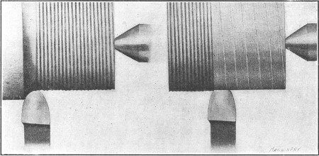
Fig. 15. Roughing Cut—Light Finishing Cut and Coarse Feed
The amount of feed to use for a finishing cut might, properly, be
either fine or coarse. Ordinarily, fine feeds are used for finishing
steel, especially if the work is at all flexible, whereas finishing cuts
in cast iron are often accompanied by a coarse feed. Fig. 15 illustrates the feeds that are often used when turning
cast iron. The view to the left shows a deep roughing cut and
the one to the right, a finishing cut. By using a broad flat
cutting edge set parallel to the tool's travel, and a coarse feed
for finishing, a smooth cut can be taken in a comparatively
short time. Castings which are close to the finished size in
the rough can often be finished to advantage by taking a single
cut with a broad tool, provided the work is sufficiently rigid.
It is not always practicable to use these broad tools and coarse
feeds, as they sometimes cause chattering, and when used on
steel, a broad tool tends to gouge or “dig in” unless the part
being turned is rigid. Heavy steel parts, however, are sometimes
finished in this way. The modern method of finishing
many steel parts is to simply rough them out in a lathe to
within, say, 1/32 inch of the required diameter and take the finishing
cut in a cylindrical grinding machine.
Effect of Lubricant on Cutting Speed.—When
turning iron or steel a higher cutting speed can be used, if a stream
of soda water or other cooling lubricant falls upon the chip at the
point where it is being removed by the tool. In fact, experiments have
shown that the cutting speed, when using a large stream of cooling water
and a high-speed steel tool, can be about 40 percent higher than when
turning dry or without a cooling lubricant. For ordinary carbon steel
tools, the gain was about 25 per cent. The most satisfactory results
were obtained from a stream falling at a rather slow velocity but in
large volume. The gain in cutting speed, by the use of soda water or
other suitable fluids, was found to be practically the same for all
qualities of steel from the softest to the hardest.
Cast iron is usually turned dry or without a cutting lubricant.
Experiments, however, made to determine the effect of applying
a heavy stream of cooling water to a tool turning cast iron,
showed the following results: Cutting speed without water, 47
feet per minute; cutting speed with a heavy stream of water,
nearly 54 feet per minute; increase in speed, 15 per cent. The
dirt caused by mixing the fine cast-iron turnings with a cutting
lubricant is an objectionable feature which, in the opinion of
many, more than offsets the increase in cutting speed that
might be obtained.
Turret lathes and automatic turning machines are equipped
with a pump and piping for supplying cooling lubricant to the
tools in a continuous stream. Engine lathes used for general
work, however, are rarely provided with such equipment and
a lubricant, when used, is often supplied by a can mounted at
the rear of the carriage, having a spout which extends above the
tool. Owing to the inconvenience in using a lubricant on an
engine lathe, steel, as well as cast iron, is often turned dry
especially when the work is small and the cuts light and comparatively
short.
Lubricants Used for Turning.—A
good grade of lard oil is an excellent lubricant for use when turning
steel or wrought iron and it is extensively used on automatic screw
machines, especially those which operate on comparatively small work.
For some classes of work, especially when high-cutting speeds are used,
lard oil is not as satisfactory as soda water or some of the commercial
lubricants, because the oil is more sluggish and does not penetrate to
the cutting point with sufficient rapidity. Many lubricants which are
cheaper than oil are extensively used on “automatics” for general
machining operations. These usually consist of a mixture of sal-soda
(carbonate of soda) and water, to which is added some ingredient such as
lard oil or soft soap to thicken or give body to the lubricant.
A cheap lubricant for turning, milling, etc., and one that has
been extensively used, is made in the following proportions:
1 pound of sal-soda, 1 quart of lard oil, 1 quart of soft soap,
and enough water to make 10 or 12 gallons. This mixture is
boiled for one-half hour, preferably by passing a steam coil
through it. If the solution should have an objectionable odor,
this can be eliminated by adding 2 pounds of unslaked lime. The
soap and soda in this solution improve the lubricating quality
and also prevent the surfaces from rusting. For turning and
threading operations, plain milling, deep-hole drilling, etc., a
mixture of equal parts of lard oil and paraffin oil will be found
very satisfactory, the paraffin being added to lessen the expense.
Brass or bronze is usually machined dry, although lard oil is
sometimes used for automatic screw machine work. Babbitt
metal is also worked dry, ordinarily, although kerosene or
turpentine is sometimes used when boring or reaming. If
babbitt is bored dry, balls of metal tend to form on the tool
point and score the work. Milk is generally considered the best
lubricant for machining copper. A mixture of lard oil and
turpentine is also used for copper. For aluminum, the following
lubricants can be used: Kerosene, a mixture of kerosene
and gasoline, soap-water, or “aqualine” one part, water 20
parts.
Lard Oil as a Cutting Lubricant.—After
being used for a considerable time, lard oil seems to lose some of its
good qualities as a cooling compound. There are several reasons for
this: Some manufacturers use the same oil over and over again on
different materials, such as brass, steel, etc. This is objectionable,
for when lard oil has been used on brass it is practically impossible to
get the fine dust separated from it in a centrifugal separator. When
this impure oil is used on steel, especially where high-speed steels are
employed, it does not give satisfactory results, owing to the fact that
when the cutting tool becomes dull, the small brass particles “freeze”
to the cutting tool and thus produce rough work. The best results are
obtained from lard oil by keeping it thin, and by using it on the same
materials—that is, not transferring the oil from a machine in which
brass is being cut to one where it would be employed on steel. If the
oil is always used on the same class of material, it will not lose any
of its good qualities.
Prime lard oil is nearly colorless, having a pale yellow or
greenish tinge. The solidifying point and other characteristics
of the oil depend upon the temperature at which it was expressed,
winter-pressed lard oil containing less solid constituents of the
lard than that expressed in warm weather. The specific gravity
should not exceed 0.916; it is sometimes increased by adulterants,
such as cotton-seed and maize oils.
Return to Contents