|
Turning and Boring on a Lathe
Online Reprint Chapter 6
This a complete book, published in
1914, divided into chapters on how to use a metal lathe, covering all
turning and boring operations.
|
Return to Contents
Turning and Boring
by Franklin D. Jones
Published by Industrial Press 1914
A special treatise for machinists students in industrial and
engineering schools, and apprentices on turning and boring methods
including modern practice with engine lathes, vertical, and horizontal
boring machines.
Shop Amazon.com
|
CHAPTER VI
VERTICAL BORING MILL PRACTICE
All the different types of turning machines now in use originated
from the lathe. Many of these tools, however, do not resemble the lathe
because, in the process of evolution, there have been many changes made
in order to develop turning machines for handling certain classes of
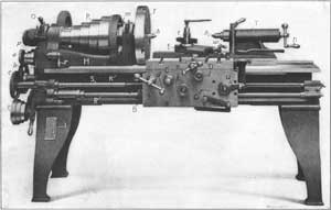
work to the best advantage. The machine illustrated in Fig. 1
belongs to the lathe family and is known as a vertical boring and
turning mill. This type, as the name implies, is used for boring and
turning operations, and it is very efficient for work within its range.
The part to be machined is held to the table B either by clamps
or in chuck jaws attached to the table. When the machine is in
operation, the table revolves and the turning or boring tools (which are
held in tool-blocks T) remain stationary, except for the feeding
movement. Very often more than one tool is used at a time, as will be
shown later by examples of vertical boring mill work. The tool-blocks T are inserted in tool-bars T1 carried by saddles S which are mounted on cross-rail C. Each tool-head (consisting of a saddle and tool-bar) can be moved horizontally along cross-rail C, and the tool-bars T1 have a vertical movement. These movements can be effected either by hand or power.
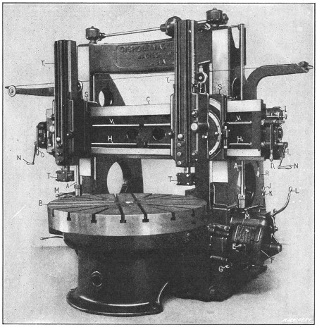
Fig. 1. Gisholt Vertical Boring and Turning Mill
When a surface is being turned parallel to the work table, the
entire tool-head moves horizontally along the cross-rail, but when a
cylindrical surface is being turned, the tool-bar moves vertically. The
tool-heads are moved horizontally by the screws H and H1, and the vertical feed for the tool-bars is obtained from the splined shafts V and V1,
there being a separate screw and shaft for each head so that the
feeding movements are independent. These feed shafts are rotated for the
power feed by vertical shafts A and A1 on each
side of the machine. These vertical shafts connect with the feed shafts
through bevel and spur gears located at the ends of the cross-rail. On
most boring mills, connection is made with one of the splined shafts V or screw H,
by a movable gear, which is placed on whichever shaft will give the
desired direction of feed. The particular machine illustrated is so
arranged that either the right or left screw or feed shaft can be
engaged by simply shifting levers D1 or D.
The amount of feed per revolution of the table is varied for each tool-head by feed-changing mechanisms F
on each side of the machine. These feed boxes contain gears of
different sizes, and by changing the combinations of these gears, the
amount of feed is varied. Five feed changes are obtained on this machine
by shifting lever E, and this number is doubled by shifting lever G.
By having two feed boxes, the feeding movement of each head can be
varied independently. The direction of either the horizontal or vertical
feed can be reversed by lever R, which is also used for engaging or disengaging the feeds. This machine is equipped with the dials I and I1
which can be set to automatically disengage the feed at any
predetermined point. There are also micrometer dials graduated to
thousandths of an inch and used for adjusting the tools without the use
of measuring instruments.
The work table B is driven indirectly from a belt pulley at
the rear, which transmits the power through gearing. The speed of the
table can be varied for turning large or small parts, by levers J and K and the table can be started, stopped or rotated part of a revolution by lever L
which connects with a friction clutch. There are corresponding feed and
speed levers on the opposite side, so that the machine can be
controlled from either position.
The heads can be adjusted along the cross-rail for setting the tools by hand-cranks N, and the tool slides can be moved vertically by turning shafts V
with the same cranks. With this machine, however, these adjustments do
not have to be made by hand, ordinarily, as there are rapid power
movements controlled by levers M. These levers automatically
disengage the feeds and enable the tool-heads to be rapidly shifted to
the required position, the direction of the movement depending upon the
position of the feed reverse lever R and lever D. This
rapid traverse, which is a feature applied to modern boring mills of
medium and large size, saves time and the labor connected with hand
adjustments. The cross-rail C has a vertical adjustment on the
faces of the right and left housings which support it, in order to
locate the tool-heads at the right height for the work. This adjustment
is effected by power and is controlled by levers at the sides of the
housings. Normally, the cross-rail is bolted to the housings, and these
bolts must be loosened before making the adjustment, and must always be
tightened afterwards.
The function of these different levers has been explained to show,
in a general way, how a vertical boring machine is operated. It should
be understood, however, that the arrangement differs considerably on
machines of other makes. The construction also varies considerably on
machines of the same make but of different size.
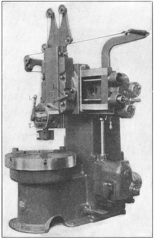
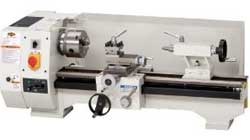
Fig. 2. Small Boring and Turning Mill
with Single Turret-head
All modern vertical boring mills of medium and large sizes are equipped with two tool-heads, as shown in Fig. 1,
because a great deal of work done on a machine of this type can have
two surfaces machined simultaneously. On the other hand, small mills of
the type illustrated in Fig. 2 have a single head. The toolslide of this machine, instead of having a single tool-block, carries a five-sided turret T
in which different tools can be mounted. These tools are shifted to the
working position as they are needed, by loosening binder lever L and turning or “indexing” the turret. The turret is located and locked in any of its five positions by lever I,
which controls a plunger that engages notches at the rear. Frequently,
all the tools for machining a part can be held in the turret, so that
little time is required for changing from one tool to the next. Some
large machines having two tool-heads are also equipped with a turret on
one head.
Boring and Turning in a Vertical Boring Mill.—The vertical
boring mill is, in many respects, like a lathe placed in a vertical
position, the table of the mill corresponding to the faceplate or chuck
of the lathe and the tool-head to the lathe carriage. Much of the work
done by a vertical mill could also be machined in a lathe, but the
former is much more efficient for work within its range. To begin with,
it is more convenient to clamp work to a horizontal table than to the
vertical surface of a lathe faceplate, or, as someone has aptly said,
“It is easier to lay a piece down than to hang it up.” This is
especially true of the heavy parts for which the boring mill is
principally used. Very deep roughing cuts can also be taken with a
vertical mill. This type of machine mill is designed for turning and
boring work which, generally speaking, is quite large in diameter in
proportion to the width or height. The work varies greatly, especially
in regard to its diameter, so that boring mills are built in a large
range of sizes. The small and medium sizes will swing work varying from
about 30 inches to 6 or 7 feet in diameter, whereas large machines, such
as are used for turning very large flywheels, sheaves, etc., have a
swing of 16 or 20 feet, and larger sizes are used in some shops. The
size of a vertical mill, like any other machine tool, should be somewhat
in proportion to the size of the work for which it is intended, as a
very large machine is unwieldy, and, therefore, inefficient for
machining comparatively small parts.
Holding and Setting Work on Boring Mill Table.—There
are three general methods of holding work to the table of a boring
mill; namely, by the use of chucks, by ordinary bolts and clamps, or in
special fixtures. Chucks which are built into the table (as illustrated
in Fig. 2) and have both universal and
independent adjustments for the jaws can be used to advantage for
holding castings that are either round or irregular in shape. The
universal adjustment is used for cylindrical parts, such as disks,
flywheels, gear blanks, etc., and the independent adjustment, for
castings of irregular shape. Chucks which have either an independent or
universal movement for the jaws are known as a “combination” type and
usually have three jaws. There is also a four-jaw type which has the
independent adjustment only. This style is preferable for work that is
not cylindrical and which must be held very securely. Chuck jaws that do
not form a part of the machine table, but are bolted to it in the
required position, are also employed extensively, especially on
comparatively large machines.
Most of the work done in a vertical mill is held in a chuck.
Occasionally, however, it is preferable to clamp a part directly to the
table. This may be desirable because of the shape and size of the work,
or because it is necessary to hold a previously machined surface
directly against the table in order to secure greater accuracy.
Sometimes a casting is held in the chuck for turning one side, and then
the finished side is clamped against the table for turning the opposite
side. Parts which are to be machined in large quantities are often held
in special fixtures. This method is employed when it enables the work to
be set up more quickly than would be possible if regular clamps or
chuck jaws were used.
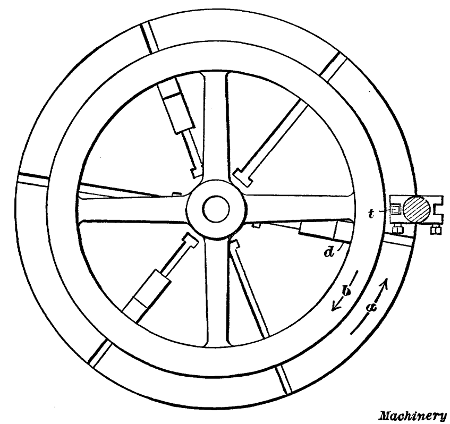
Fig. 3. Plan View showing Flywheel Casting Chucked for Turning
Work that is to be turned or bored should first be set so that the
part to be machined is about central with the table. For example, the
rim of a flywheel should be set to run true so that it can be finished
by removing about the same amount of metal around the entire rim; in
other words, the rim should be set concentric with the table, as shown
in Fig. 3, and the sides of the rim should also be parallel to the table.
A simple tool that is very useful for testing the position of any
cylindrical casting consists of a wooden shank into which is inserted a
piece of wire, having one end bent. This tool is clamped in the toolpost
and as the work revolves the wire is adjusted close to the cylindrical
surface being tested. The movement of the work with relation to the
stationary wire point will, of course, show whether or not the part runs
true. The advantage of using a piece of wire for testing, instead of a
rigid tool, is that the wire, owing to its flexibility, will simply be
bent backward if it is moved too close to a surface which is
considerably out of true. The upper surface of a casting can be tested
for parallelism with the table by using this same wire gage, or by
comparing the surface, as the table is revolved slowly, with a tool held
in the toolpost. An ordinary surface gage is also used for this
purpose. The proper surface to set true, in any case, depends upon the
requirements. A plain cylindrical disk would be set so that the outside
ran true and the top surface was parallel with the table. When setting a
flywheel, if the inside of the rim is to remain rough, the casting
should be set by this surface rather than by the outside, so that the
rim, when finished, will be uniform in thickness.
As far as possible, chucks should be used for holding cylindrical
parts, owing to their convenience. The jaws should be set against an
interior cylindrical surface whenever this is feasible. To illustrate,
the flywheel in Fig. 3 is gripped by the inside
of the rim which permits the outside to be turned at this setting of the
work. It is also advisable to set a flywheel casting in the chuck so
that a spoke rests against one of the jaws as at d, if this is
possible. This jaw will then act as a driver and prevent the casting
from slipping or turning in the chuck jaws, owing to the tangential
pressure of the turning tool. When a cut is being taken, the table and
work rotate as shown by arrow a, and the thrust of the cut (taken by tool t) tends to move the wheel backward against the direction of rotation, as shown by arrow b.
If one of the chuck jaws bears against one of the spokes, this movement
is prevented. It is not always feasible to use a chuck jaw as a driver
and then a special driver having the form of a small angle-plate or
block is sometimes bolted directly to the table. Another method of
driving is to set a brace between a spoke or projection on the work and a
chuck jaw or strip attached to the table. Drivers are not only used
when turning flywheels, but in connection with any large casting,
especially when heavy cuts have to be taken. Of course, some castings
are so shaped that drivers cannot be employed.
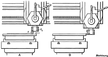
Fig. 4. (A) Turning a Flat Surface.
(B) Turning a Cylindrical Surface
Turning in a Boring Mill.—The vertical type of boring mill
is used more for turning cylindrical surfaces than for actual boring,
although a large part of the work requires both turning and boring. We
shall first consider, in a general way, how surfaces are turned and then
refer to some boring operations. The diagram A, Fig. 4, illustrates how a horizontal surface would be turned. The tool t is clamped in tool-block t1,
in a vertical position, and it is fed horizontally as the table and
work rotate. The tool is first adjusted by hand for the proper depth of
cut and the automatic horizontal feed is then engaged. When a
cylindrical surface is to be turned, the tool (provided a straight tool
is used) is clamped in a horizontal position and is fed downward as
indicated at B. The amount that the tool should feed per
revolution of the work, depends upon the kind of material being turned,
the diameter of the turned part and the depth of the cut.
Most of the parts machined in a vertical boring mill are made of
cast iron and, ordinarily, at least one roughing and one finishing cut
is taken. The number of roughing cuts required in any case depends, of
course, upon the amount of metal to be removed. An ordinary roughing cut
in soft cast iron might vary in depth from 1/8 or 3/16 inch to 3/8 or 1/2 inch and the tool would probably have a feed per revolution of from 1/16 to 1/8
inch, although deeper cuts and coarser feeds are sometimes taken. These
figures are merely given to show, in a general way, what cuts and feeds
are practicable. The tool used for roughing usually has a rounded end
which leaves a ridged or rough surface. To obtain a smooth finish, broad
flat tools are used. The flat cutting edge is set parallel to the
tool's travel and a coarse feed is used in order to reduce the time
required for taking the cut. The finishing feeds for cast iron vary from
1/4 to 3/4 inch on ordinary work. The different tools used on the vertical mill will be referred to more in detail later.
All medium and large sized vertical boring mills are equipped with
two tool-heads and two tools are frequently used at the same time,
especially on large work. Fig. 9 illustrates the
use of two tools simultaneously. The casting shown is a flywheel, and
the tool on the right side turns the upper side of the rim, while the
tool on the left side turns the outside or cylindrical surface. As a
boring mill table rotates in a counter-clockwise direction, the
left-hand tool is reversed to bring the cutting edge at the rear. By
turning two surfaces at once, the total time for machining the casting
is, of course, greatly reduced. The turning of flywheels is a common
vertical boring mill operation, and this work will be referred to in
detail later on.
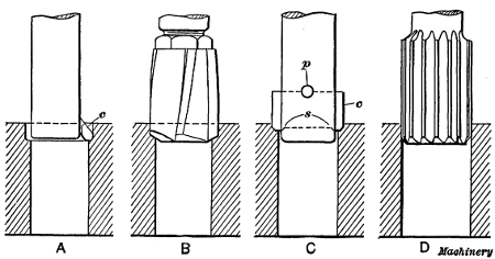
Fig. 5. Tools for Boring and Reaming Holes
Boring Operations.—There are several methods of machining
holes when using a vertical boring mill. Ordinarily, small holes are
cored in castings and it is simply necessary to finish the rough surface
to the required diameter. Some of the tools used for boring and
finishing comparatively small holes are shown in Fig. 5. Sketch A shows a boring tool consisting of a cutter c
inserted in a shank, which, in turn, is held in the tool slide, or in a
turret attached to the tool slide. With a tool of this type, a hole is
bored by taking one or more cuts down through it. The tool shown at B
is a four-lipped drill which is used for drilling cored holes
preparatory to finishing by a cutter or reamer. This drill would
probably finish a hole to within about 1/32 inch of the finish diameter, thus leaving a small amount of metal for the reamer to remove. The tool illustrated at C has a double-ended flat cutter c,
which cuts on both sides. These cutters are often made in sets for
boring duplicate parts. Ordinarily, there are two cutters in a set, one
being used for roughing and the other for finishing. The cutter passes
through a rectangular slot in the bar and this particular style is
centrally located by shoulders s, and is held by a taper pin p.
Some cutter bars have an extension end, or “pilot” as it is called,
which passes through a close-fitting bushing in the table to steady the
bar. Sketch D shows a finishing reamer. This tool takes a very
light cut and is intended to finish holes that have been previously
bored close to the required size. Sometimes a flat cutter C is
used for roughing and a reamer for finishing. The reamer is especially
desirable for interchangeable work, when all holes must have a smooth
finish and be of the same diameter. When a reamer is held rigidly to a
turret or toolslide, it is liable to produce a hole that is either
tapering or larger than the reamer diameter. To prevent this, the reamer
should be held in a “floating” holder which, by means of a slight
adjustment, allows the reamer to align itself with the hole. There are
several methods of securing this “floating” movement. (See “Floating Reamer Holders.”)
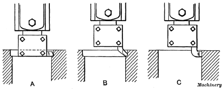
Fig. 6. Boring with Regular Turning Tools
Large holes or interior cylindrical surfaces are bored by tools
held in the regular tool-head. The tool is sometimes clamped in a
horizontal position as shown at A, Fig. 6, or a bent type is used as at B. Cast iron is usually finished by a broad flat tool as at C,
the same as when turning exterior surfaces. Obviously a hole that is
bored in this way must be large enough to admit the tool-block.
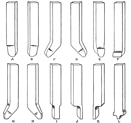
Fig. 7. Set of Boring Mill Tools
Turning Tools for the Vertical Boring Mill.—A set of turning tools for the vertical boring mill is shown in Fig. 7.
These tools can be used for a wide variety of ordinary turning
operations. When a great many duplicate parts are to be machined,
special tool equipment can often be used to advantage, but as the form
of this equipment depends upon the character of the work, only standard
tools have been shown in this illustration. The tool shown at A is a right-hand, roughing tool, and a left-hand tool of the same type is shown at B. Tool C is an offset or bent, left-hand round nose for roughing, and D is a right-hand offset roughing tool. A straight round nose is shown at E. Tool F has a flat, broad cutting edge and is used for finishing. Left-and right-hand finishing tools of the offset type are shown at G and H, respectively. Tool I has a square end and is used for cutting grooves. Right-and left-hand parting tools are shown at J and K, and tool L is a form frequently used for rounding corners.
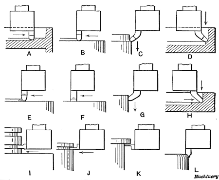
Fig. 8. Diagrams Illustrating Use of Different Forms of Tools
The diagrams in Fig. 8 show, in a general way, how each of the tools illustrated in Fig. 7
are used, and corresponding tools are marked by the same reference
letters in both of these illustrations. The right-and left-hand roughing
tools A and B are especially adapted for taking deep
roughing cuts. One feeds away from the center of the table, or to the
right (when held in the right-hand tool-block) and the other tool is
ground to feed in the opposite direction. Ordinarily, when turning plain
flat surfaces, the cut is started at the outside and the tool feeds
toward the center, as at B, although it is sometimes more convenient to feed in the opposite direction, as at A, especially when there is a rim or other projecting part at the outside edge. The tool shown at A
could also be used for turning cylindrical surfaces, by clamping it in a
horizontal position across the bottom of the tool-block. The feeding
movement would then be downward or at right-angles to the work table.
The offset round-nose tools C and D are for turning
exterior or interior cylinder surfaces. The shank of this tool is
clamped in the tool-block in a vertical position and as the bent end
extends below the tool-block, it can be fed down close to a shoulder.
The straight type shown at E is commonly used for turning steel
or iron, and when the point is drawn out narrower, it is also used for
brass, although the front is then ground without slope. Tool F is
for light finishing cuts and broad feeds. The amount of feed per
revolution of the work should always be less than the width of the
cutting edge as otherwise ridges will be left on the turned surface. The
offset tools G and H are for finishing exterior and
interior cylindrical surfaces. These tools also have both vertical and
horizontal cutting edges and are sometimes used for first finishing a
cylindrical and then a horizontal surface, or vice versa. Tool I
is adapted to such work as cutting packing-ring grooves in engine
pistons, forming square or rectangular grooves, and similar work. The
parting tools J and K can also be used for forming narrow grooves or for cutting off rings, etc. The sketch K (Fig. 8) indicates how a tool of this kind might be used for squaring a corner under a shoulder. Tool L
is frequently used on boring mills for rounding the corners of flywheel
rims, in order to give them a more finished appearance. It has two
cutting edges so that either side can be used as when rounding the inner
and outer corners of a rim.
The turning tools of a vertical boring mill are similar, in many
respects, to those used in a lathe, although the shanks of the former
are shorter and more stocky than those of lathe tools. The cutting edges
of some of the tools also differ somewhat in form, but the principles
which govern the grinding of lathe and boring mill tools are identical,
and those who are not familiar with tool grinding are referred to Chapter II, in which this subject is treated.
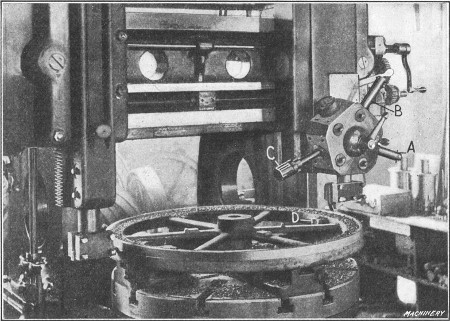
Fig. 9. Turning the Rim of a Flywheel
Turning a Flywheel on a Vertical Mill.—The turning of a
flywheel is a good example of the kind of work for which a vertical
boring mill is adapted. A flywheel should preferably be machined on a
double-head mill so that one side and the periphery of the rim can be
turned at the same time. A common method of holding a flywheel is shown
in Fig. 9. The rim is gripped by four chuck jaws D
which, if practicable, should be on the inside where they will not
interfere with the movement of the tool. Two of the jaws, in this case,
are set against the spokes on opposite sides of the wheel, to act as
drivers and prevent any backward shifting of work when a heavy cut is
being taken. The illustration shows the tool to the right rough turning
the side of the rim, while the left-hand tool turns the periphery.
Finishing cuts are also taken over the rim, at this setting, and the hub
is turned on the outside, faced on top, and the hole bored.
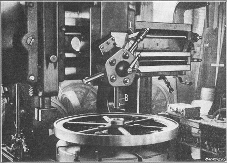
Fig. 10. Tool B set for Boring the Hub
The three tools A, B and C, for finishing the hole, are mounted in the turret. Bar A, which carries a cutter at its end, first rough bores the hole. The sizing cutter B is then used to straighten it before inserting the finishing reamer C. Fig. 10 shows the turret moved over to a central position and the sizing cutter B
set for boring. The head is centrally located (on this particular
machine) by a positive center-stop. The turret is indexed for bringing
the different tools into the working position, by loosening the clamping
lever L and pulling down lever I which disengages the
turret lock-pin. When all the flywheels in a lot have been machined as
described, the opposite side is finished.
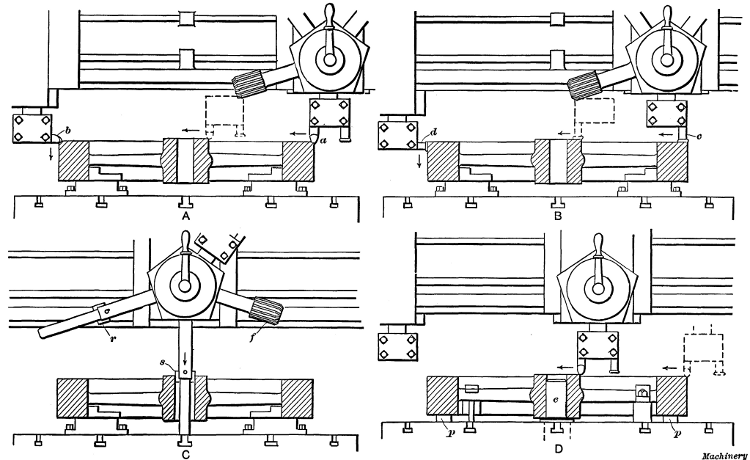
Fig. 11. Diagrams showing Method of Turning and Boring a Flywheel on a Double-head Mill having one Turret Head
In order to show more clearly the method of handling work of this
class, the machining of a flywheel will be explained more in detail in
connection with Fig. 11, which illustrates practically the same equipment as is shown in Figs. 9 and 10. The successive order in which the various operations are performed is as follows: Tool a (see sketch A) rough turns the side of the rim, while tool b,
which is set with its cutting edge toward the rear, rough turns the
outside. The direction of the feeding movement for each tool is
indicated by the arrows. When tool a has crossed the rim, it is
moved over for facing the hub, as shown by the dotted lines. The side
and periphery of the rim are next finished by the broad-nose finishing
tools c and d (see sketch B). The feed should be increased for finishing, so that each tool will have a movement of say 1/4 or 3/8
inch per revolution of the work, and the cuts should, at least, be deep
enough to remove the marks made by the roughing tools. Tool c is
also used for finishing the hub as indicated by the dotted lines. After
these cuts are taken, the outside of the hub and inner surface of the
rim are usually turned down as far as the spokes, by using offset tools
similar to the ones shown at C and D in Fig. 7. The corners of the rim and hub are also rounded to give the work a more finished appearance, by using a tool L.
The next operation is that of finishing the hole through the hub. The hard scale is first removed by a roughing cutter r (sketch C), which is followed by a “sizing” cutter s. The hole is then finished smooth and to the right diameter by reamer f. The bars carrying cutters r and s
have extensions or “pilots” which enter a close-fitting bushing in the
table, in order to steady the bar and hold it in alignment.
When the hole is finished, the wheel is turned over, so that the
lower side of the rim and hub can be faced. The method of holding the
casting for the final operation is shown at D. The chuck jaws are removed, and the finished side of the rim is clamped against parallels p resting on the table. The wheel is centrally located for turning this side by a plug e
which is inserted in a hole in the table and fits the bore of the hub.
The wheel is held by clamps which bear against the spokes. Roughing and
finishing cuts are next taken over the top surface of the rim and hub
and the corners are rounded, which completes the machining operations.
If the rim needs to be a certain width, about the same amount of metal
should be removed from each side, unless sandy spots or “blow-holes” in
the casting make it necessary to take more from one side than from the
other. That side of the rim which was up in the mold when the casting
was made should be turned first, because the porous, spongy spots
usually form on the “cope” or top side of a casting.
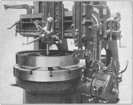
Fig. 12. Gisholt Mill equipped with Convex Turning Attachment
Convex Turning Attachment for Boring Mills.—Fig. 12
shows a vertical boring mill arranged for turning pulleys having convex
rims; that is, the rim, instead of being cylindrical, is rounded
somewhat so that it slopes from the center toward either side. (The
reason for turning a pulley rim convex is to prevent the belt from
running off at one side, as it sometimes tends to do when a cylindrical
pulley is used.) The convex surface is produced by a special attachment
which causes the turning tool to gradually move outward as it feeds
down, until the center of the rim is reached, after which the movement
is inward.
The particular attachment shown in Fig. 12 consists of a special box-shaped tool-head F containing a sliding holder G,
in which the tool is clamped by set-screws passing through elongated
slots in the front of the tool-head. In addition, there is a radius link
L which swivels on a stud at the rear of the tool-head and is attached to vertical link H. Link L is so connected to the sliding tool-block that any downward movement of the tool-bar I
causes the tool to move outward until the link is in a horizontal
position, after which the movement is reversed. When the attachment is
first set up, the turning tool is placed at the center of the rim and
then link L is clamped to the vertical link while in a horizontal
position. The cut is started at the top edge of the rim, and the tool
is fed downward by power, the same as when turning a cylindrical
surface. The amount of curvature or convexity of a rim can be varied by
inserting the clamp bolt J in different holes in link L.
The tools for machining the hub and sides of the rim are held in a
turret mounted on the left-hand head, as shown. The special tool-holder A
contains two bent tools for turning the upper and lower edges of the
pulley rim at the same time as the tool-head is fed horizontally.
Roughing and finishing tools B are for facing the hub, and the tools C, D, and E rough bore, finish bore, and ream the hole for the shaft.
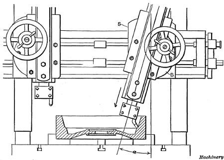
Fig. 13. Turning a Taper or Conical Surface
Turning Taper or Conical Surfaces.—Conical or taper surfaces are turned in a vertical boring mill by swiveling the tool-bar to the proper angle as shown in Fig. 13. When the taper is given in degrees, the tool-bar can be set by graduations on the edge of the circular base B, which show the angle a to which the bar is swiveled from a vertical position. The base turns on a central stud and is secured to the saddle S
by the bolts shown, which should be tightened after the tool-bar is
set. The vertical power feed can be used for taper turning the same as
for cylindrical work.
Fig. 14. Turning a Conical Surface by using the
Combined Vertical and Horizontal Feeds
Occasionally it is necessary to machine a conical surface which has
such a large included angle that the tool-bar cannot be swiveled far
enough around to permit turning by the method illustrated in Fig. 13.
Another method, which is sometimes resorted to for work of this class,
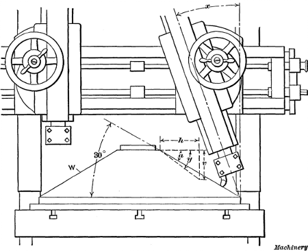
is to use the combined vertical and horizontal feeds. Suppose we want to
turn the conical casting W (Fig. 14), to an angle of 30 degrees, as shown, and that the tool-head of the boring mill moves horizontally 1/4 inch per turn of the feed-screw and has a vertical movement of 3/16 inch per turn of the upper feed-shaft. If the two feeds are used simultaneously, the tool will move a distance h of say 8 inches, while it moves downward a distance v of 6 inches, thus turning the surface to an angle y.
This angle is greater (as measured from a horizontal plane) than the
angle required, but, if the tool-bar is swiveled to an angle x,
the tool, as it moves downward, will also be advanced horizontally, in
addition to the regular horizontal movement. The result is that the
angle y is diminished and if the tool-bar is set over the right amount, the conical surface can be turned to an angle a of 30 degrees. The problem, then, is to determine what the angle x should be for turning to a given angle a.
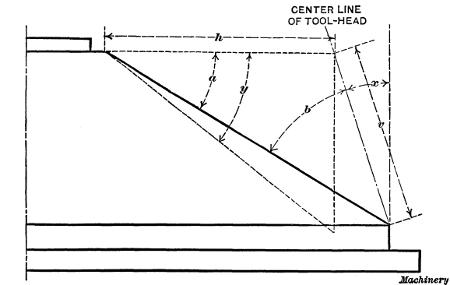
Fig. 15. Diagram showing Method of Obtaining Angular Position
of Tool-head when Turning Conical Surfaces by using Vertical and
Horizontal Feeding Movements
The way angle x is calculated will be explained in connection with the enlarged diagram, Fig. 15, which shows one-half of the casting. The sine of the known angle a is first found in a table of natural sines. Then the sine of angle b, between the taper surface and center-line of the tool-head, is determined as follows: sin b = (sin a × h) ÷ v, in which h represents the rate of horizontal feed and v the rate of vertical feed. The angle corresponding to sine b is next found in a table of sines. We now have angles b and a, and by subtracting the sum of these angles from 90 degrees, the desired angle x is obtained. To illustrate:
The sine of 30 degrees is 0.5; then sin b = (0.5 × 1/4) ÷ 3/16 = 0.6666; hence angle b = 41 degrees 49 minutes, and x = 90° - (30° + 41° 49') = 18 degrees 11 minutes. Hence to turn the casting to angle a
in a boring mill having the horizontal and vertical feeds given, the
tool-head would be set over from the vertical 18 degrees and 11 minutes
which is equivalent to about 181/6 degrees.
If the required angle a were greater than angle y
obtained from the combined feeds with the tool-bar in a vertical
position, it would then be necessary to swing the lower end of the bar
to the left rather than to the right of a vertical plane. When the
required angle a exceeds angle y, the sum of angles a and b is greater than 90 degrees so that angle x for the tool-head = (a + b) - 90 degrees.
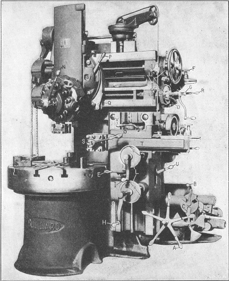
Fig. 16. Bullard Vertical Turret Lathe
Turret-lathe Type of Vertical Boring Mill.—The machine illustrated in Fig. 16
was designed to combine the advantages of the horizontal turret lathe
and the vertical boring mill. It is known as a “vertical turret lathe,”
but resembles, in many respects, a vertical boring mill. This machine
has a turret on the cross-rail the same as many vertical boring mills,
and, in addition, a side-head S. The side-head has a vertical feeding movement, and the tool-bar T
can be fed horizontally. The tool-bar is also equipped with a
four-sided turret for holding turning tools. This arrangement of the
tool-heads makes it possible to use two tools simultaneously upon
comparatively small work. When both heads are mounted on the cross-rail,
as with a double-head boring mill, it is often impossible to machine
certain parts to advantage, because one head interferes with the other.
The drive to the table (for the particular machine illustrated) is
from a belt pulley at the rear, and fifteen speed changes are available.
Five changes are obtained by turning the pilot-wheel A and this series of five speeds is compounded three times by turning lever B. Each spoke of pilot-wheel A indicates a speed which is engaged only when the spoke is in a vertical position, and the three positions for B are indicated, by slots in the disk shown. The number of table revolutions per minute for different positions of pilot-wheel A and lever B are shown by figures seen through whichever slot is at C.
There are five rows of figures corresponding to the five spokes of the
pilot-wheel and three figures in a row, and the speed is shown by arrows
on the sides of the slots. The segment disk containing these figures
also serves as an interlocking device which prevents moving more than
one speed controlling lever at a time, in order to avoid damaging the
driving mechanism.
The feeding movement for each head is independent. Lever D
controls the engagement or disengagement of the vertical or cross feeds
for the head on the cross-rail. The feed for the side-head is controlled
by lever E. When this lever is pushed inward, the entire head
feeds vertically, but when it is pulled out, the tool-bar feeds
horizontally. These two feeds can be disengaged by placing the lever in a
neutral position. The direction of the feeding movement for either head
can be reversed by lever R. The amount of feed is varied by feed-wheel F and clutch-rod G. When lever E is in the neutral position, the side-head or tool-bar can be adjusted by the hand-cranks H and I,
respectively. The cross-rail head and its turret slide have rapid power
traverse movements for making quick adjustments. This rapid traverse is
controlled by the key-handles J.
The feed-screws for the vertical head have micrometer dials K for making accurate adjustments. There are also large dials at L
which indicate vertical movements of the side head and horizontal
movements of the tool slide. All of these dials have small adjustable
clips c which are numbered to correspond to numbers on the faces
of the respective turrets. These clips or “observation stops” are used
in the production of duplicate parts. For example, suppose a tool in
face No. 1 for the main turret is set for a given diameter and height of
shoulder on a part which is to be duplicated. To obtain the same
setting of the tools for the next piece, clips No. 1, on both the
vertical feed rod and screw dials, are placed opposite the graduations
which are intersected by stationary pointers secured to the cross-rail.
The clips are set in this way after the first part has been machined to
the required size and before disturbing the final position of the tools.
For turning a duplicate part, the tools are simply brought to the same
position by turning the feed screws until the clips and stationary
pointers again coincide. For setting tools on other faces of either
turret, this operation is repeated, except that clips are used bearing
numbers corresponding to the turret face in use.
The main turret of this machine has five holes in which are
inserted the necessary boring and turning tools, drills or reamers, as
may be required. By having all the tools mounted in the turret, they can
be quickly and accurately set in the working position. When the turret
is indexed from one face to the next, binder lever N is first
loosened. The turret then moves forward, away from its seat, thus
disengaging the indexing and registering pins which accurately locate it
in any one of the five positions. The turret is revolved by turning
crank M, one turn of this handle moving the turret 1/5 revolution or from one hole to the next. The side-head turret is turned by loosening lever O. The turret slide can be locked rigidly in any position by lever P and its saddle is clamped to the cross-rail by lever Q. The binder levers for the saddle and toolslide of the side-head are located at U and V,
respectively. A slide that does not require feeding movements is locked
in order to obtain greater rigidity. To illustrate, if the main tool
slide were to feed vertically and not horizontally, it might be
advisable to lock the saddle to the cross-rail, while taking the
vertical cut.
The vertical slide can be set at an angle for taper turning, and
the turret is accurately located over the center of the table for boring
or reaming, by a positive center stop. The machine is provided with a
brake for stopping the work table quickly, which is operated by lifting
the shaft of pilot-wheel A. The side-and cross-rails are a unit
and are adjusted together to accommodate work of different heights. This
adjustment is effected by power on the particular machine illustrated,
and it is controlled by a lever near the left end of the cross-rail.
Before making this adjustment, all binder bolts which normally hold the
rails rigidly to the machine column must be released, and care should be
taken to tighten them after the adjustment is made.
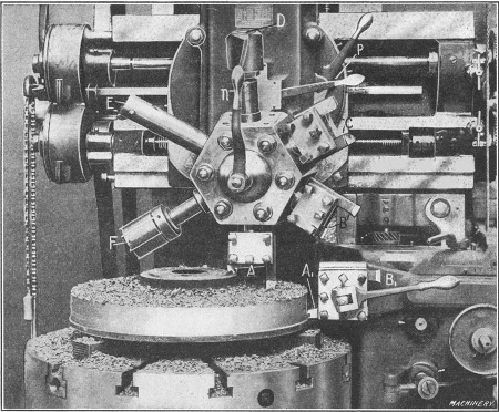
Fig. 17. Turning a Gear Blank on a Vertical Turret Lathe
Examples of Vertical Turret Lathe Work.—In order to
illustrate how a vertical turret lathe is used, one or two examples of
work will be referred to in detail. These examples also indicate, in a
general way, the class of work for which this type of machine is
adapted. Fig. 17 shows how a cast-iron gear
blank is machined. The work is gripped on the inside of the rim by three
chuck jaws, and all of the tools required for the various operations
are mounted in the main and side turrets. The illustration shows the
first operation which is that of rough turning the hub, the top side of
the blank and its periphery. The tools A for facing the hub and upper surface are both held in one tool-block on the main turret, and tool A1 for roughing the periphery is in the side turret. With this arrangement, the three surfaces can be turned simultaneously.
The main turret is next indexed one-sixth of a revolution which brings the broad finishing tools B into position, and the side turret is also turned to locate finishing tool B1
at the front. (The indexing of the main turret on this particular
machine is effected by loosening binder lever n and raising the turret
lock-pin by means of lever p.) The hub, side and periphery of the blank are then finished. When tools B
are clamped in the tool-blocks, they are, of course, set for turning
the hub to the required height. The third operation is performed by the
tools at C, one of which “breaks” or chamfers the corner of the cored hole in the hub, to provide a starting surface for drill D, and the other turns the outside of the hub, after the chamfering tool is removed. The four-lipped shell-drill D
is next used to drill the cored hole and then this hole is bored close
to the finished size and concentric with the circumference of the blank
by boring tool E, which is followed by the finishing reamer F.
When the drill, boring tool and reamer are being used, the turret is
set over the center or axis of the table, by means of a positive center
stop on the left-side of the turret saddle. If it is necessary to move
the turret beyond the central position, this stop can be swung out of
the way.
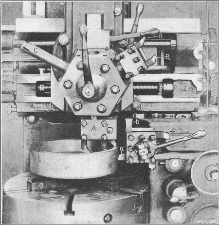
Fig. 18. Turning Gasoline Engine Flywheel on Vertical Turret Lathe—First Position
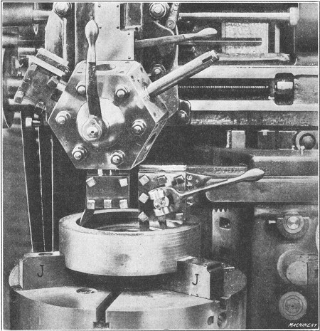
Fig. 19. Turning Gasoline Engine Flywheel—Second Position
Figs. 18 and 19
illustrate the turning of an automobile flywheel, which is another
typical example of work for a machine of this type. The flywheel is
finished in two settings. Its position for the first series of
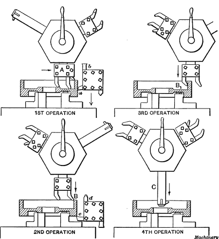
operations is shown in Fig. 18, and the successive order of the four operations for the first setting is shown by the diagrams, Fig. 20. The first operation requires four tools which act simultaneously. The three held in tool-block A of the turret, face the hub, the web and the rim of the flywheel, while tool a in the side-head rough turns the outside diameter. The outside diameter is also finished by broad-nosed tool b which is given a coarse feed. In the second operation, the under face of the rim is finished by tool c, the outer corners are rounded by tool d and the inner surface of the rim is rough turned by a bent tool B,
which is moved into position by indexing the main turret. In the third
operation, the side-head is moved out of the way and the inside of the
rim is finished by another bent tool B1. The final operation at this setting is the boring of the central hole, which is done with a bar C having interchangeable cutters which make it possible to finish the hole at one setting of the turret.
Fig. 20. Diagrams showing How Successive Operations
are Performed by Different Tools in the Turret
The remaining operations are performed on the opposite side of the work which is held in “soft” jaws J accurately bored to fit the finished outside diameter as indicated in Fig. 19.
The tool in the main turret turns the inside of the rim, and the
side-head is equipped with two tools for facing the web and hub
simultaneously. As the tool in the main turret operates on the left side
of the rim, it is set with the cutting edge toward the rear. In order
to move the turret to this position, which is beyond the center of the
table, the center stop previously referred to is swung out of the way.
Floating Reamer Holders.—If a reamer is held rigidly in the
turret of a boring mill or turret lathe, it is liable to produce a hole
which tapers slightly or is too large. When a hole is bored with a
single-point boring tool, it is concentric with the axis of rotation,
and if a reamer that is aligned exactly with the bored hole is fed into
the work, the finished hole should be cylindrical and the correct size.
It is very difficult, however, to locate a reamer exactly in line with a
bored hole, because of slight variations in the indexing of the turret,
or errors resulting from wear of the guiding ways or other important
parts of the machine.
To prevent inaccuracies due to this cause, reamers are often held
in what is known as a “floating” holder. This type of holder is so
arranged that the reamer, instead of being held rigidly, is allowed a
slight free or floating movement so that it can follow a hole which has
been bored true, without restraint. In this way the hole is reamed
straight and to practically the same size as the reamer.
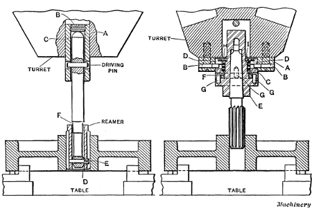
Fig. 21. Two Types of Floating Reamer Holders
There are many different designs of floating holders but the
general principle upon which they are based is illustrated by the two
types shown in Fig. 21. The reamer and holder shown to the left has a ball-shank A which bears against a backing-up screw B inserted in the end of holder C through which the driving pin passes. The lower end of the reamer shank is also spherical-shaped at D, and screw-pin E secures the shell reamer to this end. It will be noted that the hole in the shank for pin E is “bell-mouthed” on each side of the center and that there is clearance at F
between the shank and reamer shell; hence the reamer has a free
floating action in any direction. This holder has given very
satisfactory results.
The holder shown to the right is attached to the face of the turret by four fillister-head screws. Sleeve C is held in plate A by means of two steel pins B which are tight in plate A and made to fit freely in bayonet grooves D. Reamer holder E floats on sleeve C, the floating motion being obtained through the four steel pins G extending into driving ring F. Two of the pins are tight in the holder E and two in sleeve C. The faces of sleeve C, driving ring F, and reamer holder E are held tightly against each other by means of spring H which insures the reamer being held perfectly true. Spring H is adjusted by means of nut I
which is turned with a spanner wrench furnished with each holder. The
reamer is so held that its axis is always maintained parallel to the
center of the hole, and, at the same time, it has a slight
self-adjusting tendency radially, so that the hole and reamer will
automatically keep in perfect alignment with each other.
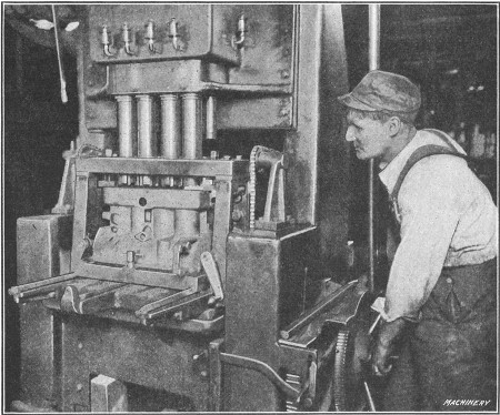
Fig. 22. Multiple-spindle Cylinder Boring Machine
Multiple Cylinder Boring Machine.—In automobile and other
factories where a great many gasoline engine cylinders are required,
multiple-spindle boring machines of the vertical type are commonly used.
The machine shown in Fig. 22 is a special design for boring four cylinders which are cast en bloc
or in one solid casting. The work is held in a box jig which has a top
plate equipped with guide bearings for holding the spindles rigidly
while boring. The lower end of each spindle has attached to it a
cutter-head and the boring is done by feeding the table and casting
vertically. This feeding movement is effected by power and it is
disengaged automatically when the cutters have bored to the required
depth. The particular machine illustrated is used for rough boring only,
the cylinders being finished by reaming in another similar machine. The
cylinders are bored to a diameter of 35/8 inches, and about 3/8
inch of metal is removed by the roughing cut. The spindles have fixed
center-to-center distances as the machine is intended for constant use
on cylinders of one size, so that adjustment is not necessary. Of
course, a special machine of this kind is only used in shops where large
numbers of cylinders of one design are required continually. Some
cylinder boring machines of the vertical type have spindles which can be
adjusted for different center-to-center distances if this should be
necessary in order to accommodate a cylinder of another size.
Return to Contents