|
Turning and
Boring on a Lathe
Online Reprint Chapter 5
This a complete book, published
in 1914, divided into chapters on how to use a metal lathe,
covering all turning and boring operations.
|
Return to Contents
Turning and Boring
by Franklin D. Jones
Published by Industrial Press 1914
A special treatise for machinists students in industrial and
engineering schools, and apprentices on turning and boring methods
including modern practice with engine lathes, vertical, and horizontal
boring machines.
Shop Amazon.com
|
CHAPTER V
TURRET LATHE PRACTICE
Turret lathes are adapted for turning duplicate parts in quantity.
The characteristic feature of a turret lathe is the turret which is
mounted upon a carriage and contains the tools which are successively
brought into the working position by indexing or rotating the turret. In
many instances, all the tools required can be held in the turret,
although it is often necessary to use other tools, held on a
cross-slide, for cutting off the finished part, facing a radial surface,
knurling, or for some other operation. After a turret lathe is equipped
with the tools needed for machining a certain part, it produces the
finished work much more rapidly than would be possible by using an
ordinary engine lathe, principally because each tool is carefully set
for turning or boring to whatever size is required and the turret makes
it possible to quickly place any tool in the working position. Turret
lathes also have systems of stops or gages for controlling the travel of
the turret carriage and cross-slide, in order to regulate the depth of a
bored hole, the length of a cylindrical part or its diameter; hence,
turning machines of this type are much more efficient than ordinary
lathes for turning duplicate parts, unless the quantity is small, in
which case, the advantage of the turret lathe might be much more than
offset by the cost of the special tool equipment and the time required
for “setting up” the machine. (See “Selecting Type of Turning Machine.”)
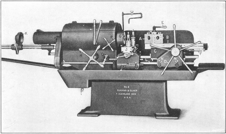
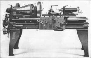
Fig. 1. Bardons & Oliver Turret Lathe of Motor-driven Geared-head Type
General Description of a Turret Lathe.—The turret lathe shown in Fig. 1 has a hexagonal shaped turret A with a hole in each side in which the tools are held. This turret is mounted on a slide B which is carried by a saddle C
that can be moved along the bed to locate the turret slide with
reference to the length of the tools in the turret and the room required
for indexing. The turret slide can be moved longitudinally by turning
the pilot wheel or turnstile D, or it can be fed by power.
Ordinarily, the hand adjustment is used for quickly moving the carriage
when the tools are not cutting, although sometimes the hand feed is
preferable to a power feed when the tools are at work, especially if the
cuts are short. After a turret tool has finished its cut, the turnstile
is used to return the slide to the starting point, and at the end of
this backward movement the turret is automatically indexed or turned
one-sixth of a revolution, thus bringing the next tool into the working
position. The turret is accurately located in each of its six positions
by a lock bolt which engages notches formed in a large index ring at the
turret base. A binder lever E at the top of the turret stud is used to clamp the turret rigidly to the slide when the tools are cutting.
The forward movement of the slide for each position of the turret is controlled by stops at F,
which are set to suit the work being turned. When parts are being
turned from bar stock, the latter passes through the hollow spindle of
the headstock and extends just far enough beyond the end of the spindle
to permit turning one of the parts. The bar is held while the turning
tools are at work, by a chuck of the collet type at G. This chuck is opened or closed around the bar by turning handwheel H. After a finished part has been cut off by a tool held in cross-slide J, the chuck is released and further movement of wheel H causes ratchet feed dog K,
and the bar which passes through it, to be drawn forward. This forward
movement is continued until the end of the bar comes against a stop gage
held in one of the turret holes, to insure feeding the bar out just the
right amount for turning the next piece. On some turret lathes, the
lever which operates the chuck also controls a power feed for the bar
stock, the latter being pushed through the spindle against the stop.
The machine illustrated has a power feed for the cross-slide as
well as for the turret. The motion is obtained from the same shaft L which actuates the turret slide, but the feed changes are independent. The cross-slide feed changes are varied by levers M and those for the turret by levers N.
For many turret lathe operations, such as turning castings, etc., a
jawed chuck is screwed onto the spindle and the work is held the same as
when a chuck is used on an engine lathe. Sometimes chucks are used
having special jaws for holding castings of irregular shape, or special
work-holding fixtures which are bolted to the faceplate. The small
handle at O is for moving the cross-slide along the bed when this is necessary in order to feed a tool sidewise.
This particular machine is driven by a motor at the rear of the
headstock, connection being made with the spindle through gearing. The
necessary speed changes are obtained both by varying the speed of the
motor and by shifting gears in the headstock. The motor is controlled by
the turnstile P and the gears are shifted by the vertical levers shown.
While many of the features referred to are common to turret lathes
in general, it will be understood that the details such as the control
levers, arrangement of stops, etc., vary on turret lathes of different
make.
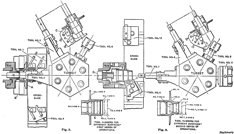
Figs. 2 and 3. Diagrams showing Turret Lathe Tool Equipment for Machining Automobile Hub Casting
Example of Turret Lathe Work.—The diagrams Figs. 2 and 3
show a turret lathe operation which is typical in many respects. The
part to be turned is a hub casting for an automobile and it is machined
in two series of operations. The first series is shown by the plan view,
Fig. 2. The casting A is held in a three-jaw chuck B.
Tool No. 1 on the cross-slide is equipped with two cutters and rough
faces the flange and end, while the inner and outer surfaces of the
cylindrical part are rough bored and turned by combination boring and
turning tool No. 2. This tool has, in addition to a regular boring-bar, a
bracket or tool-holder which projects above the work and carries
cutters that operate on the top surface. Tools Nos. 3 and 4 next come
into action, No. 3 finishing the surfaces roughed out by No. 2, and No. 4
finish-facing the flange and end of the hub. The detailed side view of
Tool No. 3 (which is practically the same as No. 2), shows the
arrangement of the cutters C and D, one of which turns the
cylindrical surface and the other bevels the end of the hub. The hole
in the hub is next finished by tool No. 5 which is a stepped reamer that
machines the bore and counterbore to the required size within very
close limits. The surfaces machined by the different tools referred to
are indicated by the sectional view E of the hub, which shows by the numbers what tools are used on each surface.
For the second series of operations, the position of the hub is
reversed and it is held in a spring or collet type of chuck as shown by
the plan view Fig. 3. The finished cylindrical end of the hub is inserted in the split collet F which is drawn back into the tapering collet ring by rod G (operated by turnstile H, Fig. 1)
thus closing the collet tightly around the casting. The first operation
is that of facing the side of the flange and end of the hub with tool
No. 6 on the cross-slide, which is shown in the working position. A
broad cutter H is used for facing the flange and finishing the large fillet, and the end is faced by a smaller cutter I.
When these tools are withdrawn, tool No. 7 is moved up for rough
turning the outside of the cylindrical end (preparatory to cutting a
thread) and rough boring the hole. These same surfaces are then finished
by tool No. 8. The arrangement of tools Nos. 7 and 8 is shown by the
detailed view. Tool J turns the part to be threaded; tool K turns the end beyond the threaded part; and tool L
bevels the corner or edge. The reaming tool No. 9 is next indexed to
the working position for finishing the hole and beveling the outer edge
slightly. At the same time, the form tool No. 10, held at the rear of
the cross-slide, is fed up for beveling the flange to an angle of 60
degrees. The final operation is that of threading the end, which is done
with die No. 11. The boring-bars of tools Nos. 2, 3, 7 and 8 are all
provided with pilots N which enter close fitting bushings held in
the spindle, to steady the bar while taking the cut. This is a common
method of supporting turret lathe tools.
The feed of the turret for both the first and second series of operations is 1/27
inch per revolution and the speeds 60 revolutions per minute for the
roughing cuts and 90 revolutions per minute for the finishing cuts. The
total time for machining one of these castings complete is about 71/2 minutes, which includes the time required for placing the work in the chuck.
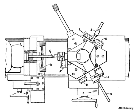
Fig. 4. First Cycle of Operations in Finishing Gasoline Engine
Flywheels on a Pond Turret Lathe
Machining Flywheels in Turret Lathe.—Figs. 4 to 6,
inclusive,illustrate how a gasoline engine flywheel is finished all
over in two cycles of operations. First the flywheel is turned complete
on one side, the hole bored and reamed, and the outside of the rim
finished; in the second cycle the other side of the flywheel is
completed.
During the first operation, the work is held by the inside of the
rim by means of a four-jaw chuck equipped with hard jaws. The side of
the rim, the tapering circumference of the recess, the web, and the hub
are first rough-turned, using tools held in the carriage toolpost. The
hole is then rough-bored by bar C, which is supported in a bushing in the chuck, as shown in Fig. 4. The outside of the wheel rim is rough-turned at the same time by a cutter held in the extension turret tool-holder T (Fig. 5), and the taper fit on the inside of the flywheel is turned by means of cutter A (Fig. 4) held in a tool-holder attached to the turret.
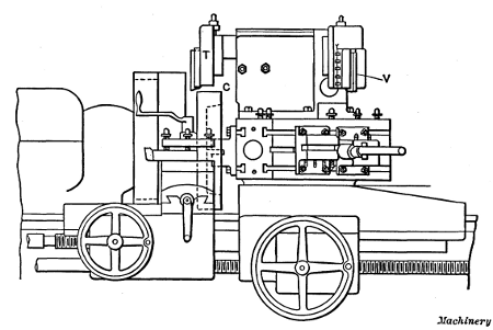
Fig. 5. Elevation of Turret and Tools for Finishing Flywheels—First Operation
The outside of the wheel rim is next finish-turned with cutter V (Fig. 5) held in an extension turret tool-holder the same as the roughing tool T. At the same time, the bore is finished by a cutter in boring-bar D (Fig. 4). The side of the rim and the hub of the wheel are also finished at this time by two facing cutters H and K,
held in tool-holders on the face of the turret. When the finishing cuts
on the rim and hub are being taken, the work is supported by a bushing
on the boring-bar which enters the bore of the wheel, the boring cutter
and facing tools being set in such relation to each other that the final
boring of the hole is completed before the facing cuts are taken.
The web of the wheel is next finish-faced with the facing cutter held in the holder E, and the taper surface on the inside of the rim is finished by the tool L, at the same time. While these last operations are performed, the work is supported by a bushing on a supporting arbor J, which enters the bore of the wheel. The bore is finally reamed to size by a reamer F held in a “floating” reamer-holder. When the reaming operation is completed, a clearance groove N is cut on the inside of the rim, using a tool G held in the carriage toolpost. The first cycle of operations on the flywheel is now completed.
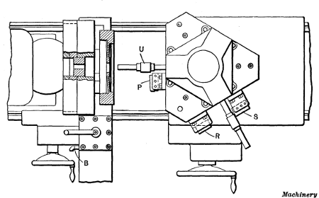
Fig. 6. Second Cycle of Operations on Flywheel
The flywheel is then removed from the chuck, turned around, and
held in “soft” jaws for the second cycle of operations, the jaws fitting
the outside of the wheel rim. (Soft unhardened jaws are used to prevent
marring the finished surface of the rim.) The operations on this side
are very similar to those performed on the other side. First, the side
of the rim, the inside of the rim, the web, and hub are rough-turned,
using tools held in the carriage toolpost. The inside of the rim and the
web are then finished by a cutter held in a tool-holder at P, Fig. 6,
which is bolted to the face of the turret. The work is supported during
this operation by a bushing held on a supporting arbor U, having a pilot which enters a bushing in the chuck. Finally, the rim and hub are finished, by the facing cutters R and S, the work being supported by an arbor, as before.
These operations illustrate the methods employed in automobile
factories, and other shops where large numbers of engine flywheels,
etc., must be machined.
Fig. 7. Turret Lathe Tool Equipment for Machining Flywheels
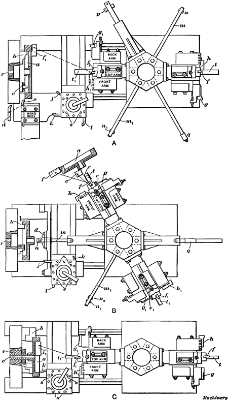
Finishing a Flywheel at One Setting in Turret Lathe.—The plan view A, Fig. 7,
shows an arrangement of tools for finishing a flywheel complete at one
setting. The hole for the shaft has to be bored and reamed and the hub
faced on both sides. The sides and periphery of the rim also have to be
finished and all four corners of the rim rounded. The tools for doing
this work consist of boring-bars, a reamer, facing heads on the main
turret, a turret toolpost on the slide rest (carrying, in this case,
three tools) and a special supplementary wing rest attached to the front
of the carriage at the extreme left.
The casting is held by three special hardened jaws b in a
universal chuck. These jaws grip the work on the inner side of the rim,
leaving room for a tool to finish the rear face without striking the
chuck body or jaws. Three rests c are provided between the chuck
jaws. The work is pressed against these rests while being tightened in
the chuck, and they serve to locate it so that the arms will run true so
far as sidewise movement is concerned. These rests also locate the
casting with relation to the stops for the turret and carriage
movements. The chuck carries a bushing r of suitable diameter to support the boring-bars in the main turret, as will be described.
In the first operation, boring-bar m is brought in line with the spindle and is entered in bushing r in the chuck. Double-ended cutter n
is then fed through the hub of the pulley to true up the cored hole.
While boring the hole, the scale on the front face of the rim and hub is
removed by tool j. Tool k is then brought into action to rough turn the periphery, after which tool e,
in the wing rest, is fed down to clean up the back face of the rim. As
soon as the scale is removed, the hole is bored nearly to size by cutter
n1 in bar m1, and it is finally finished with reamer q mounted on a floating arbor.
The cutters f, g and h, in the facing head,
are next brought up to rough face the hub and rim, and round the corners
of the rim on the front side. This operation is all done by broad
shaving cuts. The facing head in which the tools are held is provided
with a pilot bar t which fits the finished hole in the flywheel hub, and steadies the head during the operation. The cutters f, g and h
are mounted in holders which may be so adjusted as to bring them to the
proper setting for the desired dimensions. This completes the roughing
operations.
The periphery of the rim is now finished by cutter l in the
turret toolpost which is indexed to the proper position for this
operation. The rear face of the rim is finished by the same tool e with which the roughing was done. Tool e is then removed and replaced with d which rounds the inner corner of the rim. Tool d
is also replaced with a third tool for rounding the outer corner of the
rear side. For finishing the front faces of the rim and hub and
rounding the corners of the rim, a second facing head, identical with
the first one, is employed. This is shown in position in the
illustration. Cutters f1, g1 and h1 correspond with the cutters f, g and h, previously referred to, and perform the same operations.
The remaining operation of finishing the back of the hub is effected by cutter p.
This cutter is removed from the bar, which is then inserted through the
bore; the cutter is then replaced in its slot and the rear end of the
hub is faced by feeding the carriage away from the headstock. This
completes the operations, the flywheel being finished at one setting.
Finishing a Webbed Flywheel in Two Settings.—The plan views B and C, Fig. 7,
show the arrangement of tools for finishing a webbed flywheel which has
to be machined all over. This, of course, requires two operations. In
the first of these (see sketch B) the rough casting is chucked on the inside of the rim with regular inside hard chuck jaws b. The cored hole is first rough bored with cutter n attached to the end of boring-bar m, and guided by the drill support d pivoted to the carriage. Next, the boring-bar m1 is brought into position, the drill support being swung back out of the way. This bar is steadied by its bearing in bushing r in the chuck. Two cutters, n1 and n2,
are used to roughly shape the hole to the desired taper, the small end
being finished to within 0.002 inch of the required diameter. While
boring with the bar m1, the scale is broken on the web and hub of the casting by the tool k in the turret toolpost. The latter is then shifted to bring the tool j into position for removing the scale on the periphery of the wheel. Next, the hole is reamed with taper reamer q, the pilot of which is supported by bushing r.
The first of the facing heads is now brought into action. This facing head carries a guide t which is steadied in a taper bushing c, driven into the taper hole of the hub for that purpose. The top cutter f turns the periphery, cutter g turns the hub and faces the web, and cutter h faces the rim. A fourth cutter e on the under side of the head faces the hub. This casting is now machined approximately to size.
For finishing, similar cutters, e1, f1, g1 and h1, in the other facing head are used, the latter being supported by the taper bushing c in the same way. A very light cut is taken for finishing. Tool l
in the carriage turret is used to round the outer and inner corners of
the rim, which completes the work on this face of the casting.
In the second cycle of operations, shown at C, the casting is chucked on the outside with the soft jaws b, which are bored to the exact diameter of the finished rim. The work is further supported and centered by sliding bushing c, which is tapered to fit the finished hole in the hub, and has an accurate bearing in bushing r
in the chuck. This bushing is provided with a threaded collar for
forcing it into the work and withdrawing it. The scale on the web and
the inside and face of the rim is first broken with the tool k in the turret toolpost. These surfaces are then roughed off with cutters f, g and h, in the facing head. This latter is steadied by a pilot t which enters the hole in the sliding bushing c on which the work is supported. A light cut is next taken with cutters f1, g1 and h1, in the finishing facing head, which completes the operation.
Tools for Turret Lathes.—The operation of a turret lathe
after the tools have been properly arranged is not particularly
difficult, but designing and making the tools, determining what order of
operations will give the most efficient and accurate results, and
setting the tools on the machine, requires both skill and experience.
For some classes of work, especially if of a rather complicated nature,
many of the tools must be specially designed, although there are certain
standard types used on turret lathes which are adapted to general
turning operations. Some of the principal types are referred to in the
following.
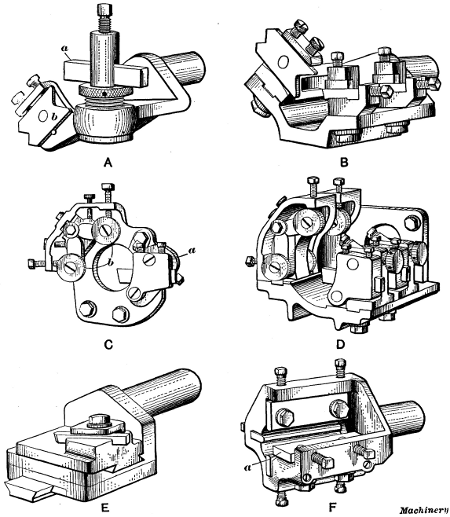
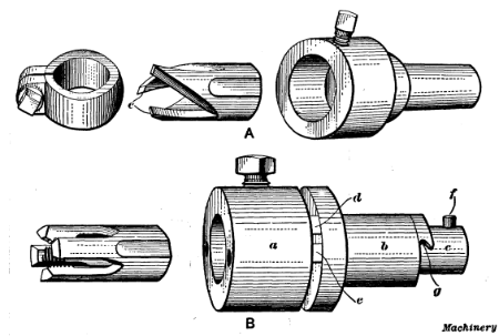
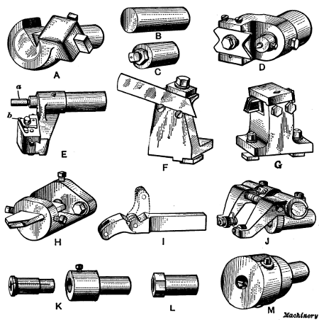
Fig. 8. Different Types of Box-tools for Turret Lathe
Box-tools.—Tools of this type are used for turning bar stock. There are many different designs, some of which are shown in Figs. 8, 9 and 10.
Box-tools are held in the turret and they have back-rests opposite the
turning tools, for supporting the part being turned. The box-tool shown
at A, Fig. 8, is for roughing. The cutter a
is a piece of high-speed steel beveled on the cutting end to produce a
keen edge. It takes a shearing tangent cut on top of the bar and the
latter is kept from springing away by means of the adjustable, hardened
tool-steel back-rest b. This tool is considered superior to a
hollow mill whenever a fair amount of stock must be removed. If
considerable smoothness and accuracy are necessary, the finishing
box-tool shown at B should follow the roughing box tool, but in
most cases, especially if the part is to be threaded by a die, a
finishing cut is unnecessary.
[192] The finishing box-tool B
is also used to follow a hollow mill if special accuracy or smoothness
is desired. This tool is only intended for light finishing cuts, the
allowances varying from 0.005 inch to 0.015 inch in diameter. The
cutters are made of square tool steel of commercial size, and are ground
and set to take a scraping end cut. This particular tool has two
tool-holders which permit finishing two diameters at once. If a larger
number of sizes must be turned, extra tool-holders can be applied.
The single-cutter box-tool shown at C is bolted directly to
the face of the turret instead of being held by a shank in the turret
hole, and it is adapted for heavy cuts such as are necessary when
turning comparatively large bar stock. The tool-holder a swivels
on a stud, thus allowing the cutter to be withdrawn from the work while
being returned, which prevents marring the turned surface. The
high-speed steel cutter is ground to take a side cut on the end of the
bar. The latter is supported by hardened and ground tool-steel rolls b
which revolve on hardened and ground studs. These rolls are mounted on
swinging arms which have a screw adjustment for different diameters.
They can also be adjusted parallel to the bar, thus enabling them to be
set either in advance of or back of the cutter. The opening in the base
allows the stock to pass into the turret when it is not larger than the
turret hole.
The box-tool shown at D is similar to the one just
described, except that it has two or more cutters and roller back-rests,
thus enabling different diameters to be turned simultaneously. The
cutters are ground to take a side cut. Ordinarily this gives a
satisfactory finish, but if special accuracy and smoothness are desired,
two tools should be used, one for roughing and one for finishing, the
latter being ground to take a light scraping end cut.
The taper-turning box-tool shown at E is designed for
accurately turning tapers on brass or cast-iron parts, when there is a
small amount of stock to be removed. The taper is obtained by cross
motion imparted to the cutter slide as the turret advances. The
taper-turning box-tool shown at F, instead of having a single-point cutter, is provided with a wide cutter a.
This tool is designed to turn tapering parts of small or medium
diameter, requiring the use of a support which cannot be provided with a
straight forming tool and holder mounted on the cut-off slide. The
cutter is backed up by the screws shown, which also provide adjustment
for different tapers within a limited range. The bar is supported by the
three back-rests shown, which also have screw adjustment.
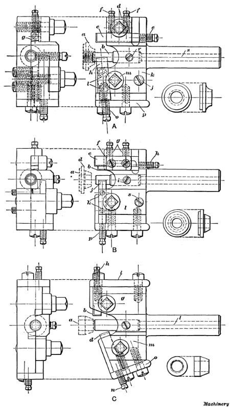
Fig. 9. Box-tools and Work for which they are Intended
Examples of Box-tool Turning.—Box-tools are not only used for cylindrical and taper turning on the end of a bar, but for many other operations. Figs. 9 and 10
show a number of box-tools of different designs, with examples of the
work for which each is intended. While these tools are designed for some
specific part, they can, of course, with slight modifications be
adapted to other work.
A box-tool of the pilot type that is used for finishing, after the
surplus stock has been removed by roughing tools, is shown at A, Fig. 9. The work, which is the cone for a ball bearing, is shown at a by the dotted lines and also by the detail view to the right. The pilot b enters the work before either of the cutters begins to operate on its respective surface. The inverted cutter c, which sizes the flange of the cone, is held in position by a clamp d, which is forced down by a collar-head screw. The cutter is further secured against a beveled shoulder at g by the set-screws f, and it is adjusted forward by the screw e. By loosening the screws f and the collar-head screw, the cutter may be removed for sharpening. The cutter h is adjusted to cut to the proper diameter, by the screws l, after which the clamp k is made level by the screw j. The collar-screw m
is then used to secure the tool in place. The cutter is made from drill
rod and it is slightly cupped out on the cutting end to give keenness
to the cutting edge. The adjusting screw o, which passes through plate p,
prevents the cutter from backing away from the work. This adjusting
screw plate has its screw holes slotted to avoid removing the screws
when it becomes necessary to remove the plate and cutter for sharpening.
Pilot b is held firmly to the tool body by set-screw r. The hole s through the shank makes it easy to remove the pilot, in case this is necessary.
A pilot box-tool for finishing another type of ball bearing cone is shown at B. The shape of the work itself is indicated by the dotted lines a and by the detail view. This tool is somewhat similar in its construction to the one just described. The cutters b and c are inverted and are used to face the flange at d and to turn it to the proper diameter. These cutters are held by the clamp f and screws g and are adjusted forward by the screw h. The cutter j, which operates on top of the stock, rests on a bolster, of the proper angle and is adjusted up or down by the screws k. The clamp l,
which binds against this tool, is beveled to correspond with the angle
of the tool. This clamp is secured by the collar-screw shown and it is
leveled by set-screws s. The adjusting screw p prevents
the cutter from slipping back. The holes in the adjusting-screw plate
are also slotted in this case so that it will not be necessary to remove
any screws when the cutter has to be taken out of the holder.
A box-tool for finishing a treadle-rod cone for a sewing machine is shown at C. This tool is also of the pilot type. The cutters in it operate on opposite sides of the cone a. The inverted cutter b sizes the cylindrical part of the cone, while the front cutter d is set at the proper angle to finish the tapered part. The rear cutter b is held in place by the clamp g and a collar screw. It is adjusted forward by the screw h in the plate i
which is held by screws as shown. The pilot is retained by a set-screw,
and it is easily removed by inserting a small rod in the hole l which passes through the shank. The cutter d is held by clamp m and is adjusted by screw n which passes through a tapped hole in plate o. The screw holes in both the adjusting plates i and o are slotted to facilitate their removal.
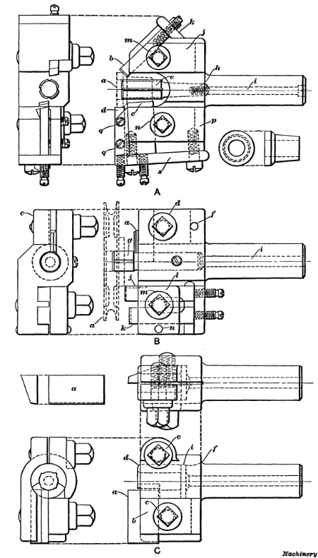
Fig. 10. Examples of Box-tool Designs
The box-tool illustrated at A, Fig. 10, is used for finishing the bushing of a double-taper cone bearing a.
The cutters are so arranged that they all cut on the center; that is,
the cutting edges lie in a horizontal plane. The inverted cutter b at the rear forms the short angular surface, and the cutter c in front forms the long tapering part of the bearing. The large diameter is turned, to size by cutter d. The pilot e
has a bearing in the bore nearly equal to the length of the work and it
is provided with oil grooves, as shown. The taper shank of this pilot
is tapped for the screw i which extends the whole length of the
shank and is used to draw the pilot back to its seat. It is not
necessary to remove adjusting-screw plate k to take out the cutter b, as the latter can be drawn out from the front after the collar-screw m is loosened. The cutter c is removed by taking off the adjusting-screw plate s after loosening the collar-screw n. The cutter d is held in a dove-tailed slot by two headless set-screws q. It is also backed up by an adjusting screw in the plate s.
These adjusting screws should all have fine threads, say from 32 to 40
per inch, and be nicely fitted so they will not loosen after being
adjusted.
The box-tools shown at B and C, Fig. 10,
are for turning the sides of a loose pulley for a sewing machine. This
pulley (shown by the dotted lines) is finished in two operations. The
box-tool for finishing the side of the pulley on which the hub projects
beyond the rim, is shown at B. The inverted cutter a, which faces the end of the hub, is held by a clamp c (clearly shown in the end view) from the under side and it has no adjustment. The collar-screw d is tapped into this clamp, which is prevented from getting out of place by the dowel-pin f. The pilot g is made small in the shank, so that tool a
can be so placed as to insure the removal of all burrs around the bore
of the hub. The pilot is held by a set-screw and it is provided with oil
grooves. The cutter j sizes the outside of the hub, and the cutter k faces the side of the pulley rim. These cutters are both held by the clamp l and the collar-screw m. No side plates are used on this tool, and the cutters are all easily removed.
Sketch C shows the box-tool used for the second operation.
As the hub is flush with the rim on the side for which this tool is
intended, it needs only one cutter to face both. This is done by the
wide cutter a which is held in a dove-tailed slot in the front of the tool and is fastened by the clamp b and collar-screw c. The bushing d, in which the end of the work arbor is supported, is held by the collar-screw e, and to obtain the necessary compression, the body of the tool is slotted as far back as f. This bushing is provided with oil grooves and one side is cut away to clear the cutter a. The pilot end of the arbor on which the work is mounted is 1/16
inch smaller than the bore of the pulley, which allows the cutter to be
set in far enough to prevent any burr which might form at the edge of
the bore. A disk i is inserted back of bushing d, so that
the latter may be easily removed by passing a rod through the hollow
shank. The special chuck used for this second operation on the loose
pulley is screwed onto the spindle, and the work is mounted on a
projecting arbor and driven by the pins engaging holes in the pulley
web. The arbor is made a driving fit for the work, and the end or pilot
is a running fit in the bushing of the box-tool. A counterbore in the
arbor hub provides clearance for the hub of the pulley which projects
beyond the rim on one side.
Fig. 11. (A) Hollow Mill and Holder.
(B) Spring Screw-threading Die and Releasing Die-holder
Hollow Mills.—A hollow mill such as is shown at A in Fig. 11
is sometimes used in place of a box-tool (especially when turning
brass) for short roughing cuts preceding a threading operation. The
turning is done by the cutting edges e, and the turned part
enters the mill and is steadied by it. If this type of tool is used for
long, straight cuts, especially on square stock and when making screws
with large heads from the bar, it should always be followed by a
finishing box-tool to insure accurate work. A hollow mill can be
sharpened readily by grinding the ends without materially changing the
cutting size. A slight adjustment can be obtained by means of the clamp
collar shown to the left, although this is not generally used. When
making these mills, they should be reamed out tapering from the rear to
give clearance to the cutting edges. For turning steel, the cutting edge
should be about 1/10 of the diameter ahead of the center, whereas for brass, it should be on the center-line.
Fig. 12. Geometric Adjustable Hollow Milling Tool
Hollow mills are also made adjustable. The design shown in Fig. 12
is especially adapted for brass finishing. It can also be used for
taking light cuts on cast iron or steel but its use in place of roughing
or finishing box-tools for general use is not recommended. With the
exception of the cutters and screws, the complete tool consists of three
parts, viz., the holder, cam, and ring. The cam serves to adjust
the cutters for different diameters. The adjustment is made by the two
screws shown, the amount being indicated by a micrometer scale. When
adjusting the cutters for a given diameter, the use of a hardened steel
plug of the required size is advisable, the cutters being adjusted
against the plug.
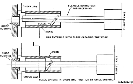
Releasing Die and Tap Holders.—Threads
are cut in the turret lathe by means of dies for external threading,
and taps for internal threading, the die or tap being held in a holder
attached to the turret. A simple form of releasing die holder is shown at B, Fig. 11. This holder was designed for the spring-screw type of threading die shown to the left. The die is clamped in the holder a by the set-screw shown, and the shank b of the holder is inserted in the turret hole. Holder a has an extension c which passes through the hollow shank. When the die is pressed against the end of the work, holder a and its extension moves back until lug d on the holder engages lug e
on the shank. The die and holder are then prevented from rotating with
the work and the die begins to cut a thread. It continues to screw
itself onto the work with the turret following, until the thread has
been cut to the required length; the turret is then stopped and as the
die and holder a are drawn forward, lugs d and e
disengage so that the die simply rotates with the work without
continuing to advance. The lathe spindle is then reversed and as the
turret is moved back by hand, pin f comes around and enters notch g,
thus holding the die stationary; the die then backs off from the
threaded end. Some tap holders are also constructed the same as this die
holder, so far as the releasing mechanism is concerned. There are also
many other designs in use, some of which operate on this same principle.
Self-opening Die Heads.—The type of die holder shown at B in Fig. 11
is objectionable because of the time required for backing the die off
the threaded end; hence, self-opening dies are extensively used in
turret lathe work. As the name implies, this type of die, instead of
being solid, has several chasers which are opened automatically when the
thread has been cut to the required length. The turret can then be
returned without reversing the lathe spindle. The dies are opened by
simply stopping the travel of the turret slide, the stop-rod for the
feed of the turret being adjusted to give the proper amount of travel.
Fig. 13. Geometric Self-opening and Adjustable Screw-cutting Die Head
A well-known die head of the self-opening type is shown in Fig. 13.
The dies open automatically as soon as the travel of the head is
retarded, or they can be opened at any point by simply holding back on
the turnstile or lever by which the turret slide is moved. The die is
closed again by means of the small handle seen projecting at
right-angles from the side of the head. The closing may be done by hand
or automatically by screwing a pin into a threaded hole opposite the
handle and attaching a small piece of flat steel to the back edge of the
turret slide. The latter will then engage the pin as the turret
revolves, thus closing the die head. This die head has a roughing and
finishing attachment which is operated by handle A. When this
handle is moved forward, the dies are adjusted outward 0.01 inch for the
roughing cut, whereas returning the handle closes and locks the dies
for the finishing cut. The die head has a micrometer scale which is used
when making slight adjustments to compensate for the wear of the
chasers or to make either a tight-or a loose-fitting thread.
Fig. 14. Geometric Collapsing Tap
Collapsing Taps.—The collapsing tap shown in Fig. 14
is one of many different designs that are manufactured. They are often
used in turret lathe practice in place of solid taps. When using this
particular style of collapsing tap, the adjustable gage A is set
for the length of thread required. When the tap has been fed to this
depth, the gage comes into contact with the end of the work, which
causes the chasers to collapse automatically. The tool is then
withdrawn, after which the chasers are again expanded and locked in
position by the handle seen at the side of the holder. In all threading
operations, whether using taps or dies, a suitable lubricant should be
used, as a better thread is obtained and there is less wear on the
tools. Lard oil is a good lubricant, although cheaper compounds give
satisfactory results on many classes of work.
Fig. 15. Various Types of Tools for the Turret Lathe
Miscellaneous Turret Lathe Tools.—The chamfering tool shown at A, Fig. 15,
is used for pointing the end of a bar before running on a roughing
box-tool. This not only finishes the end of the bar but provides an even
surface for the box-tool to start on. The cutter is beveled on the end
to form a cutting edge and it is held at an angle. The back-rest
consists of a bell-mouthed, hardened tool-steel bushing which supports
the bar while the cut is being taken.
The stop gages B and C are used in the turret to
govern the length of stock that is fed through the spindle. When a
finished piece has been cut off, the rough bar is fed through the
spindle and up against the stop gage, thus locating it for another
operation. This gage may be a plain cylindrical piece of hardened steel,
as at B, or it may have an adjusting screw as at C; for
special work, different forms or shapes are also required. The stop
gages on some machines, instead of being held in the turret, are
attached to a swinging arm or bracket that is fastened to the turret
slide and is swung up in line with the spindle when the stock is fed
forward.
The center drilling tool D is designed to hold a standard
combination center drill and reamer. This type of tool is often used
when turning parts that must be finished afterwards by grinding, to form
a center for the grinding machine. The adjustable turning tool E is used for turning the outside of gear blanks, pulley hubs or the rims of small pulleys. The pilot a enters the finished bore to steady the tool, and cutter b is adjusted to turn to the required diameter.
The cutting-off tool-holder F (which is held on the
cross-slide of the turret lathe) is usually more convenient than a
regular toolpost, as the blade can be set closer to the chuck. The blade
is held in an inclined position, as shown, to provide rake for the
cutting edge; the inclined blade can also be adjusted vertically, a
limited amount, by moving it in or out. The multiple cutting-off tool G
holds two or more blades and is used for cutting off several washers,
collars, etc., simultaneously. By changing the distance pieces between
the cutters, the latter are spaced for work of different widths. The
flat drill holder H is used for drilling short holes, and also to form a true “spot” or starting point for other drills.
Knurling tools are shown at I and J. The former is
intended for knurling short lengths and is sometimes clamped on top of
the cut-off tool on the cross-slide, the end being swung back after
knurling (as shown by the dotted lines) to prevent interference with the
work when the cutting-off tool is in operation. The knurling tool J
has a shank and is held in the turret. The two knurls are on opposite
sides of the work so that the pressure of knurling is equalized. By
adjusting the arms which hold the knurls, the tool can be set for
different diameters.
Three styles of drill holders are shown at K, L and M. Holder K
is provided with a split collet (seen to the left) which is tightened
on the drill shank by a set-screw in the holder. This holder requires a
separate collet for each size drill. The taper shank drill holder L has a standard taper hole into which the shank of the drill is inserted. The adjustable type of holder M
is extensively used, especially on small and medium sized machines when
several sizes of drills are necessary. This holder is simply a drill
chuck fitted with a special shank. For large drills the plain style of
holder K is recommended, and if only a few sizes of drills are
required, it is more satisfactory and economical than the adjustable
type.
The various types of small turret lathe tools referred to in the
foregoing for turning, threading, tapping, knurling, etc., are a few of
the many different designs of tools used in turret lathe practice.
Naturally, the tool equipment for each particular job must be changed
somewhat to suit the conditions governing each case. The tools referred
to, however, represent in a general way, the principal types used in
ordinary practice. Some of the more special tools are shown in
connection with examples of turret lathe work, which are referred to in
the following.
Fig. 16. (A) Method of Boring and Turning Pistons in Gisholt Lathe.
(B) Special Chuck and Tools for Turning, Boring and Cutting Off Eccentric Piston Rings
Turning Gasoline Engine Pistons in Turret Lathe.—The making
of pistons for gas engines, especially in automobile factories, is done
on such a large scale that rapid methods of machining them are
necessary. The plan view A, Fig. 16,
shows the turret lathe tools used in one shop for doing this work. As is
often advisable with work done in large quantities, the rough castings
are made with extra projections so arranged as to assist in holding
them. These projections are, of course, removed when the piece is
completed. In this case the piston casting a has a ring about 11/4 inch long and a little less in diameter than the piston, at the chucking end. The piston is held in suitable chuck jaws b
which are tightened against the inside of this ring. The set-screws in
these special jaws are then tightened, thus clamping the casting between
the points of the screws and the jaws. This method of holding permits
the whole exterior of the piston to be turned, since it projects beyond
the chuck jaws. This is the object in providing the piston with the
projecting ring by which it is held.
The first operation consists in rough-boring the front end of the piston. The double-ended cutter n is held in boring-bar m,
which is, in turn, supported by a drill-holder, clamped to one of the
faces of the turret. This bar is steadied by a bushing in the drill
support c which is attached to the carriage, and may be swung
into or out of the operating position, as required. After this cut is
completed, the turret is revolved half way around and the casting is
finish-bored in a similar manner, with double-ended cutter n1 held in bar m1,
the drill support being used as in the previous case. The support is
then turned back out of the way to allow the turning tools in the turret
toolpost to be used.
The outside of the piston is next rough-turned with tool k
in the turret toolpost, which is revolved to bring this cutter into
action. The toolpost is then turned to the position shown, and the
outside is finish-turned by tool j, which takes a broad shaving cut. The turret tool-holder is again revolved to bring form tool l
into position. This tool cuts the grooves for the piston rings.
Suitable positive stops are, of course, provided for both the
longitudinal and cross movements of the turret toolpost.
In the second operation, the piston a is reversed and held in soft jaws, which are used in place of the hardened jaws b
shown in the illustration. These jaws are bored to the outside diameter
of the piston, so that when closed, they hold the work true or
concentric with the lathe spindle. In this operation the chucking ring
by which the piston was previously held is cut off, and the end of the
piston is faced true. If the crank-pin hole is to be finished, a third
operation is necessary, a self-centering chuck-plate and boring and
reaming tools being used. (These are not shown in the illustration.)
Turning Piston Rings in Turret Lathe.—One method of turning piston rings is shown at B in Fig. 16. The piston rings are cut from a cast-iron cylindrical piece which has three lugs b
cast on one end and so arranged that they may be held in a three-jawed
chuck. This cylindrical casting is about 10 inches long, and when the
rings are to have their inside and outside surfaces concentric, the
casting is held by the lugs in the regular jaws furnished with the
chuck. (The arrangement used for turning and boring eccentric rings,
which is that shown in the illustration, will be described later.)
The casting a, from which the rings are made, is first rough-bored with double-ended cutter n in boring-bar m, after which it is finish-bored with cutter n1 in bar m1. While taking these cuts, the bars m and m1 are supported by their extension ends which enter bushing r located in the central hole of the chuck. This furnishes a rigid support so that a heavy cut can be taken.
The outside of the casting is next rough-turned with tool k, held in the turret toolpost. This toolpost is then revolved to bring tool j
into position, by which the outside is turned true to size, a broad
shaving chip being taken. The toolpost is again swung around, to bring
the cutting-off tool-holder l into position. This holder contains
four blades set the proper distance apart to give rings of the desired
width. Each blade, from right to left, is set a little back of the
preceding one, so that the rings are cut off one after the other, the
outer rings being supported until they are completely severed. After the
first four rings are cut off, the carriage is moved ahead to a second
stop, and four more rings are severed, this operation being continued
until the casting has been entirely cut up into rings.
When the bore of the ring is to be eccentric with the outside, the
holding arrangement shown in the illustration is used. The casting a is
bolted to a sliding chuck-plate c, and the outside is rough-turned with tool k in the toolpost. Finishing tool j is then brought into action, and the outside diameter is turned accurately to size. Then the sliding chuck-plate c, carrying the work, is moved over a distance equal to the eccentricity desired, and the work is bored with cutters n and n1 as in the previous case. The turret toolpost is next revolved and the tools l
are used for cutting off the rings. The reason for finishing the
outside first is to secure smooth rings in cutting off, as this
operation should be done when the work is running concentric with the
bore, rather than with the exterior surface.
It will be evident that this method gives a far greater output of
rings than is possible by finishing them in the more primitive way on
engine lathes. The faces of the rings may be finished in a second
operation if desired, or they may be ground, depending on the method
used in the shop where the work is being done, and the accuracy
required.
Fig. 17. Turning Gasoline Engine Pistons in Pratt & Whitney Turret Lathe
Piston Turning in Pratt and Whitney Turret Lathe.—A turret lathe equipped with tools for turning, facing and grooving automobile gasoline engine pistons is shown in Fig. 17.
The piston is held on an expanding pin chuck which is so constructed
that all of the pins are forced outward with equal pressure and
automatically conform to any irregularities on the inside of the piston.
Tool A rough-turns the outside, and just as this tool completes
its cut, a center hole is drilled and reamed in the end of the piston by
combination drill and reamer B. The turret is then indexed one-half a revolution and a finishing cut is taken by tool C. After the cylindrical body of the piston has been turned, tools held in a special holder E
attached to the cut-off slide are used to face the ends of the piston
and cut the packing-ring grooves. While the grooves are being cut, the
outer end of the piston is supported by center D. The center hole
in the end also serves to support the piston while being ground to the
required diameter in a cylindrical grinding machine. The edge at the
open end of the piston may also be faced square and the inner corner
beveled by a hook tool mounted on the rear cross-slide, although this is
usually done in a separate operation. (This provides a true surface by
which to hold this end when grinding.)
This illustration (Fig. 17) shows very clearly the stops which automatically disengage the turret feed. A bracket F is bolted to the front of the bed and contains six stop-rods G (one for each position or side of the turret). When one of these stop-rods strikes lever H, the feed is disengaged, the stop being adjusted to throw out the feed when the tool has completed its cut. Lever H is automatically aligned with the stop-rods for different sides of the turret by a cam J on the turret base. A roller K bears against this cam and, through the connecting shaft and lever shown, causes lever H to move opposite the stop-rod for whatever turret face is in the working position. Lever L is used for engaging the feed and lever R for disengaging it by hand.
The indexing of the turret at the end of the backward movement of the slide is controlled by stop M against which rod N strikes, thus disengaging the lock bolt so that the turret can turn. This stop M
is adjusted along the bed to a position depending upon the length of
the turret tools and the distance the turret must move back to allow the
tools to clear as they swing around.
Fig. 18. Pratt & Whitney Turret Lathe equipped with Special
Attachment for Turning Eccentric Piston Rings
Attachment for Turning Piston Rings.—Fig. 18
shows a special attachment applied to a Pratt & Whitney turret
lathe for turning eccentric, gas-engine piston rings. The boring of the
ring casting, turning the outside and cutting off the rings, is done
simultaneously. The interior of the casting is turned concentric with
the lathe spindle by a heavy boring-bar, the end of which is rigidly
supported by a bushing in the spindle. The slide which carries the
outside turning tool is mounted on a heavy casting which straddles the
turret. The outside of the ring casting is turned eccentric to the bore
as a result of an in-and-out movement imparted to the tool by a cam on
shaft A which is rotated from the lathe spindle through the
gearing shown. For each revolution of the work, the tool recedes from
the center and advances toward it an amount sufficient to give the
required eccentricity. When the turning and boring tools have fed
forward about 2 inches, then the cutting-off tools which are held in
holder B come into action. The end of each cutting-off tool, from
right to left, is set a little farther away from the work than the
preceding tool, so that the end rings are always severed first as the
tools are fed in by the cross-slide. A number of the completed rings may
be seen in the pan of the machine.
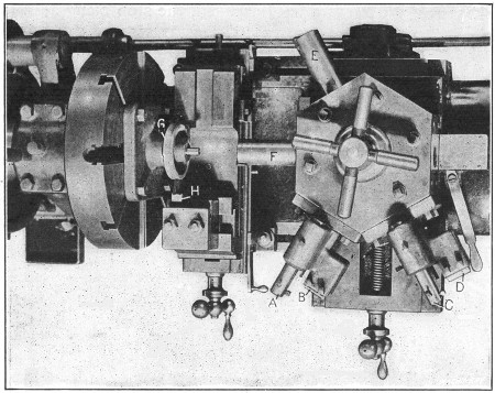
Fig. 19. Tool Equipment for Machining Worm Gear Blanks—Davis Turret Lathe
Turning Worm-gear Blanks in Turret Lathe.—This is a second operation, the hub of worm-gear blank G (Fig. 19)
having previously been bored, reamed, and faced on the rear side. The
casting is mounted upon a close-fitting arbor attached to a plate bolted
to the faceplate of the lathe, and is driven by two pins which engage
holes on the rear side. The rim is first rough-turned by a tool A which operates on top, and the side is rough-faced by a toothed or serrated cutter B. A similar tool-holder having a tool C and a smooth cutter D
is then used to turn the rim to the required diameter and finish the
side. The end of the hub is faced by cutters mounted in the end of bars E and F,
one being the roughing cutter and the other the finishing cutter. The
work arbor projects beyond the hub, as will be seen, and forms a pilot
that steadies these cutter bars. The curved rim of the gear is turned to
the required radius (preparatory to gashing and bobbing the worm-wheel
teeth) by a formed tool H held on the cross-slide.
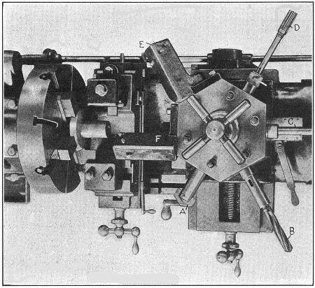
Fig. 20. Turning Bevel Gear Blanks in Davis Turret Lathe—First Operation
Turning Bevel Gear Blanks.—Fig. 20
shows a plan view of the tools used for the first turning operation on
bevel gear blanks (these gears are used for driving drill press
spindles). The cored hole is beveled true at the end by flat drill A to form a true starting surface for the three-fluted drill B which follows. The hole is bored close to the required size by a tool (not shown) held in the end of bar C, and it is finished by reamer D. The cylindrical end of the gear blank or hub is rough-and finish-turned by tools held in holders E and F,
respectively. (These holders were made to set at an angle of 45
degrees, instead of being directly over the work, as usual, so that the
cutters would be in view when setting up the machine.) It will be noted
that the chuck is equipped with special jaws which fit the beveled part
of the casting.
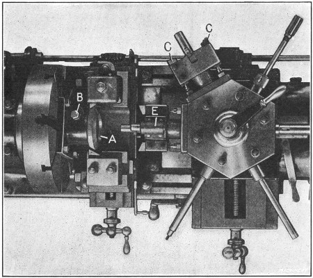
Fig. 21. Second Operation on Bevel Gear Blanks
The second and final operation on this blank is shown in Fig. 21. The work A
is held by a special driver plate attached to the faceplate of the
machine. This driver plate has two pins which engage holes drilled in
the gear blank and prevent it from rotating. The blank is also held by a
bolt B which forces a bushing against the cylindrical end.
First, the broad beveled side which is to be the toothed part of the
gear, is rough-turned by toothed cutters C, and a recess is formed in the end of the blank, by a turning tool in this same tool-holder. A similar tool-holder E,
having finishing cutters, is then used to finish the bevel face and
recess. The other tools seen in the turret are not used for this second
operation. The rear bevel is roughed and finished by tools and held on
the cross-slide.
Shell Turning Operation in Flat Turret Lathe.—The “flat
turret lathe” is so named because the turret is a flat circular plate
mounted on a low carriage to secure direct and rigid support from the
lathe bed. The tools, instead of being held by shanks inserted in holes
in the turret, are designed so that they can be clamped firmly onto the
low circular turret plate.
Fig. 22. Sectional View of Tapering Mold Shell which is turned in
Hartness Flat Turret Lathe, as illustrated in Figs. 23 to 27, Inclusive
An interesting example of flat turret lathe work is shown in Fig. 22.
This is a steel shell which must be accurately finished to a slight
taper, both inside and out, threaded and plain recesses are required at
the ends, and, in addition, one or two minor operations are necessary.
This work is done in the Hartness flat turret lathe, built by the Jones
& Lamson Machine Co. The shells are turned from cold-drawn seamless
steel tubing, having a carbon content of 0.20 per cent, and they are
finished at the rate of one in nine minutes. The tubing comes to the
machine in 12-foot lengths, and the tube being operated upon is, of
course, fed forward through the hollow spindle as each successive shell
is severed.
Fig. 23. First Operation on Shell Illustrated in Fig. 22—Rough-turning and Boring
In finishing this shell, five different operations are required.
During the first operation the shell is rough-bored and turned by one
passage of a box-tool, Fig. 23, and the recess A, Fig. 22,
at the outer end, is finished to size by a second cutter located in the
boring-bar close to the turret. The turret is then indexed to the
second station which brings the threading attachment G into position, as shown in Fig. 24. After the thread is finished, the recess B, Fig. 22, is turned by a flat cutter K, Fig. 25.
The inner and outer surfaces are then finished to size by a box-tool
mounted on the fourth station of the turret and shown in position in Fig. 26. The final operation, Fig. 27, is performed by three tools held on an auxiliary turret cross-slide, and consists in rounding the corners at b and c, Fig. 22, and severing the finished shell.
One of the interesting features connected with the machining of
this shell is the finishing of the inner and outer tapering surfaces.
The taper on the outside is 3/32 inch per foot, while the bore has a taper of only 1/64
inch per foot, and these surfaces are finished simultaneously. The
box-tool employed is of a standard type, with the exception of an
inserted boring-bar, and the taper on the outside is obtained by the
regular attachment which consists of a templet D (Fig. 23)
of the required taper, that causes the turning tool to recede at a
uniform rate as it feeds along. To secure the internal taper, the
headstock of the machine is swiveled slightly on its transverse ways by
the use of tapering gibs. By this simple method, the double taper is
finished to the required accuracy without special tools or equipment.
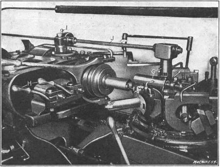
Fig. 24. Second Operation—Cutting Internal Thread
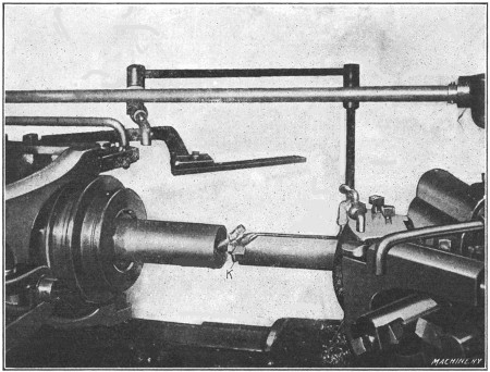
Fig. 25. Third Operation—Turning Recess at Rear End; Tool is shown withdrawn
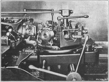
Fig. 26. Fourth Operation—Finishing the Bore and Outside
Fig. 27. Fifth Operation—Rounding Ends, Scoring Large End, and Cutting Off
As those familiar with this machine know, the longitudinal
movements of the turret as well as the transverse movements of the
headstock are controlled by positive stops. The headstock of this
machine has ten stops which are mounted in a revolving holder and are
brought into position, as required, by manipulating a lever at the
front. The stops for length, or those controlling the turret travel, are
divided into two general groups, known as “A” and “B”. Each of these
groups has six stops so that there are two stops for each of the six
positions or stations of the turret, and, in addition, five extra stops
are available for any one tool, by the engagement of a pin at the rear
of the turret. The change from the “A” to the “B” stops is made by
adjusting lever L, Fig. 26, which also has a neutral position.
After the box-tool for the roughing cut, shown at work in Fig. 23,
has reached the end of its travel, further movement is arrested by a
stop of the “A” group. The outside turning tool is then withdrawn by
operating lever E and the turret is run back and indexed to the
second station, thus bringing the threading attachment into position.
The surface speed of 130 feet per minute which is used for turning is
reduced to about 30 feet per minute for threading by manipulating levers
H, Fig. 24. After the turret is located
by another stop of the “A” group, the threading attachment is made
operative by depressing a small plunger I, which connects a vertical driving shaft from the spindle with the splined transmission shaft J. A reciprocating movement is then imparted to the thread chaser t
which advances on the cutting stroke and then automatically retreats to
clear the thread on the return. This movement is repeated until the
thread is cut to the proper depth, as determined by one of the stops for
the headstock. While the thread is being cut, the carriage is locked to
the bed by the lever N, Fig. 26. It was
found necessary to perform the threading operation before taking the
outside finishing cut, owing to a slight distortion of the shell wall,
caused by the threading operation.
After the thread is finished, the turret is turned to the third station as shown in Fig. 25, and tool K for the inner recess B, Fig. 22,
is brought into position and fed to the proper depth, as determined by
another cross-stop. The turret is also locked in position for this
operation. The finishing cuts for the bore and the outside are next
taken by a box-tool which is shown near the end of its cut in Fig. 26.
This box-tool is similar to the one used for roughing, but it is
equipped with differently shaped cutters to obtain the required finish.
The outside turning tool has a straight cutting edge set tangent to the
cylindrical surface and at an angle, while the boring tool has a cutting
edge of large radius. An end view of this box-tool is shown in Fig. 27.
A reduced feed is employed for the finishing cut, and the speed is
increased to 130 feet per minute, which is the same as that used for
roughing.
During the next and final operation, the turret, after being indexed to the position shown in Fig. 27, is first located by a stop of the “A” group so that the cutting-off tool R in front can be used for rounding the corner b, Fig. 22. The stop lever L is then shifted and the turret is moved to a second stop of the “B” group. The corner c is then rounded and the shell is scored at d by two inverted tools S and T
at the rear, after which the finished work is severed by the cut-off
tool at the front. The cross-movement of these three tools is controlled
by positive stops on the cross-slide, and the latter is moved to and
fro by hand lever O. After the shell is cut off, the stop M, mounted on the turret, Fig. 26,
is swung into position, and the tube is automatically fed forward to
the swinging stop by the roll feed, as soon as the chuck is released by
operating lever Q. This completes the cycle of operations. A
copious supply of lubricant is, of course, furnished to the tools during
these operations, and the two boring-tool shanks are hollow so that
lubricant can be forced through them and be made to play directly upon
the cutters.
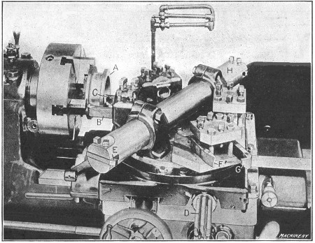
Fig. 28. Tool Equipment for Turning Scroll Gear Blank on Acme Flat Turret Lathe
Chuck Work in Flat Turret Lathe.—Two examples of chuck work on the Acme combination flat turret lathe are shown in Figs. 28 and 29. Fig. 28 shows the tool equipment for turning a cylindrical part A which is held in a three-jaw universal chuck. The front flange is first rough-turned by a bent turning tool B. The diameter is regulated by one of the cross-stops at D
which has been previously set and controls the movement of the turret
cross-slide. The longitudinal feed is disengaged when the flange has
been turned, by an independent stop. This machine has twelve
longitudinal stops, there being one for each turret face and six
auxiliary stops, in addition to the stops for the cross-slide.
After roughing the flange, the turret carriage is locked or clamped
rigidly to the bed to prevent any lengthwise movement, and the back
face of the front flange is rough-turned by tool B in to the
diameter of the hub which is indicated by a micrometer dial on the
cross-feed screw. The carriage is then unlocked and auxiliary stop No. 7
is engaged (by turning a knob at the front of the slide) and the
cylindrical hub is turned back to the rear flange, the feed being
disengaged by the auxiliary stop just as the tool reaches the flange.
The cross-slide is now moved outward, longitudinal auxiliary stop No. 8
is engaged, the turret slide is moved against the stop, the carriage is
locked and the front sides of both the front and rear flanges are
rough-faced by tools B and C. The turret is next indexed and the hole rough-bored by cutter E. After again indexing the turret, the hub and flanges are finish-turned and faced by tools F and G, as described for the rough-turning operation. The final operation is that of finishing the bore by cutter H.
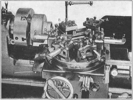
Fig. 29. Acme Flat Turret Lathe Arranged for Turning Roller Feed Body
The operation shown in Fig. 29 is that of
turning the body of a roller feed mechanism for a turret lathe. The
casting is held in a three-jaw universal chuck and it is first
rough-bored by tool A. The turret is then indexed and the side of the body and end of the hub are rough-faced by tools at B. The turret is again indexed for rough-turning the outside of the hub and body, by tools C and D. Similar tools E and F are then used to finish these same surfaces, after which the end of the hub and side of the body are finished by tools G and H similar to those located at B. The final operation is that of finishing the bore by tool J and cutting a groove in the outside of the hub by the bent tool K.
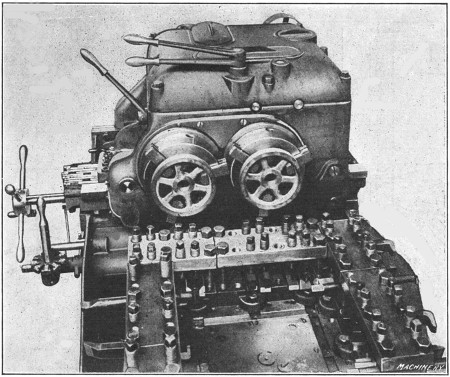
Fig. 30. Turret and Head of Jones & Lamson Double-spindle Flat Turret Lathe
Double-spindle Flat Turret Lathe.—The extent to which modern
turning machines have been developed, especially for turning duplicate
parts in quantity, is illustrated by the design of turret lathe the
turret and head of which is shown in Fig. 30.
This machine has two spindles and a large flat turret which holds a
double set of tools, so that two duplicate castings or forgings can be
turned at the same time. It was designed primarily for chuck work and
can be used as a single-spindle machine if desirable. When two spindles
are employed for machining two duplicate parts simultaneously,
considerably more time is required for setting up the machine than is
necessary for the regular single-spindle type, but it is claimed that
the increased rate of production obtained with the two-spindle design
more than offsets this initial handicap. The manufacturers consider the
single-spindle machine the best type for ordinary machine building
operations, regardless of whether the work is turned from the bar or is
of the chucking variety. On the other hand, the double-spindle type is
preferred when work is to be produced in such quantities that the time
for setting up the machine becomes a secondary consideration.
When the double-spindle machine is used as a single-spindle type, a
chuck 17 inches in diameter is used, and when both spindles are in
operation, two 9-inch chucks are employed. The general outline of the
turret is square, and the tools are rigidly held, with a minimum amount
of overhang, by means of tool-blocks and binding screws connected with
the clamping plates. Two duplicate sets of tools are clamped to each
side of the turret and these operate simultaneously on the two pieces
held in the chucks or on faceplates. Primarily the turret is used in but
four positions, but when a 17-inch chuck or faceplate is employed,
corner blocks may be held by the clamping plates in which tools are
supported, giving, if necessary, four additional operations by indexing
the turret to eight positions.
Fig. 31. Diagram showing Tool Equipment and Successive Steps
in Machining Sprocket Blanks on Double-spindle Flat Turret Lathe
A typical job to demonstrate the application of the double-spindle flat turret lathe is illustrated in Fig. 31.
The parts to be turned are sprocket wheels which are held in the two
9-inch chucks. At the first position of the turret (which is the one
illustrated), the inside is rough-bored by tools A. At the second position of the turret, tools B rough-face the inner sides of the flanges; tools C face the outer sides of the flanges, while tools D turn the faces of the flanges. At the third position of the turret, tools E finish-turn the inside of the flanges; tools F finish-turn the outside of the flanges, while tools G finish the faces of the flanges. At the fourth position of the turret, tools H finish-bore the sprockets; tools I complete the turning on the outside of the flanges, while tools J accurately size the interior of the flanges.
With the double-spindle flat turret lathe, each operation is a
double operation, and the speeds are varied according to the nature of
the cut; thus, if at one position of the turret, the tools are required
to rough out the work, this may be done rapidly, for it has no bearing
on the other operations that are subsequently performed. Furthermore, if
the following operation has to be performed with great care, this may
be done without reducing the speed of the less exacting operations.
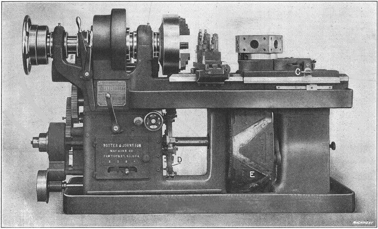
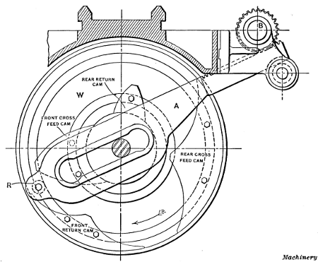
Fig. 32. Potter & Johnston Automatic Chucking and Turning Machine
Automatic Chucking and Turning Machine.—The chucking and turning machine shown in Fig. 32
is automatic in its operation, the feeding of the tools, indexing of
the turret, etc., being done automatically after the machine is properly
arranged, and the work is placed in the chuck. This machine is adapted
to turning and boring a great variety of castings, forgings or parts
from bar stock, and it is often used in preference to the hand-operated
turret lathe, especially when a great many duplicate parts are required.
It is provided with mechanism for operating the cross-slide, feeding
the turret slide forward, returning it rapidly, rotating the turret to a
new position, and feeding it forward quickly for taking a new cut. The
cross-slide and turret-slide movements are effected by cams mounted on
the large drum E seen beneath the turret, while the various speed and feed changes are effected by dogs and pins carried on disk D which is keyed to the same shaft that the cam drum is mounted upon. This shaft with the cam drum and governing disk D,
makes one revolution for each piece of work completed. The cams for
operating the turret slide are mounted upon the periphery of drum E.
The roll which engages the angular faces of these cams and imparts
movement to the turret is carried by an intermediate slide which has
rack teeth engaging a pinion on the square shaft C. By turning
this shaft with a crank, the position of the turret-slide, with relation
to the cam, may be adjusted for long or short work and long or short
tools, as may be required.
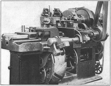
Fig. 33. Rear View of Machine showing the Cross-slide Mechanism, Driving Gearing, etc.
The cams which operate the cross-slide are mounted on the right-hand end of drum E and actuate the yoke A (see Fig. 33)
which extends diagonally upward. The rear end of this yoke has rack
teeth meshing with the teeth of a segmental pinion, which is fastened to
rock-shaft B. At the headstock end, this rock-shaft carries
another segmental pinion meshing with rack teeth formed on the
cross-slide. The movement imparted to the yoke by the cams is thus
transmitted through the pinions and rock-shaft to the cross-slide.
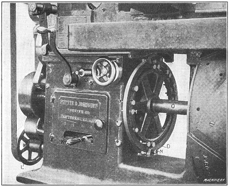
Fig. 34. The Automatic Controlling Mechanism for Feeds and Speeds
The cam drum E is driven by a pinion meshing with a gear
attached to its front side. This pinion is driven through a train of
gearing from pulley L (see Fig. 34) which
is belted to the spindle. The feeds are thus always dependent on the
spindle speed. By means of epicyclic gearing and suitable clutches, the
motion thus derived from the spindle may be made rapid for returning the
turret to be indexed and then advancing it to the cutting position
again, or very slow for the forward feed when the tools are at work.
These changes from slow to fast or vice versa are controlled by disk D.
This disk carries pins which strike a star wheel located back of the
disk at the top, and as this star wheel is turned, the speeds are
changed by operation of the gearing and clutches referred to. The first
pin M that strikes the star wheel advances it one-sixth of a
rotation, changing the feed from fast to slow; the next pin that strikes
it advances it another sixth of a rotation, changing the feed from slow
to fast and so on. By adjusting the pins for each piece of work, the
feed changes are made to take place at the proper time. Handwheel E is geared with the cam-shaft on which the star wheel is mounted, so that the feeds may be changed by hand if desired.
In addition to these feed-changing pins, disk D has a dog
which operates a lever by which the feed movement is stopped when the
work has been completed. Four rates of feed are provided by quick change
gearing of the sliding gear type, operated by handle K. With this handle set in the central position, the feed is disengaged. On the periphery of disk D are also clamped dogs or cams N, which operate a horizontal swinging lever P connected by a link with vertical lever J,
which controls the two spindle speeds with which the machine is
provided. Either one of these speeds can be automatically engaged at any
time, by adjusting the cams N on disk D.
Lever H connects or disconnects the driving pulley from the
shaft on which it is mounted, thus starting or stopping the machine. The
square shaft G serves to operate the drums by hand and is turned
with a crank. The rotation of the turret, which takes place at the rear
of its travel, is, of course, effected automatically. A dog, which may
be seen in Fig. 32 at the side of the bed, is
set to trip the turret revolving mechanism at the proper point in the
travel, to avoid interference between the tools and the work. The turret
is provided with an automatic clamping device. The mechanism first
withdraws the locking pin, unclamps the turret, revolves it, then throws
in the locking pin and clamps the turret again.
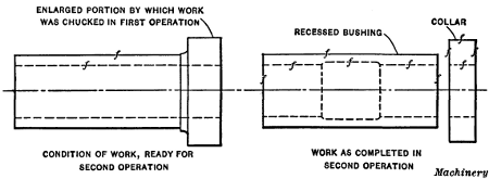
Fig. 35. Simple Example of Work done in Automatic Chucking and Turning Machine
Example of Work on Automatic Turning Machine.—The piece selected for illustrating the “setting up” and operation of the automatic chucking and turning machine is shown in Fig. 35.
This is a second operation, and a very simple one which will clearly
illustrate the principles involved. In the first operation, the hole was
drilled, bored and reamed, the small end of the bushing faced, and the
outside diameter finished, as indicated by the sketch to the left. (The
enlarged diameter at the end was used for holding the work in the
chuck.) In the second operation (illustrated to the right), the enlarged
chucking end is cut off and, in order to prevent wasting this piece, it
is made into a collar for another part of the machine for which the
bushing is intended; hence, the outside diameter is turned and the
outside end faced, before cutting off the collar. In addition, the
bushing is recessed in the second operation, and the outer end faced. In
order to have the surfaces finished in the second operation, concentric
with those machined in the first operation, the chuck is equipped with a
set of soft “false jaws” which have been carefully bored to exactly the
diameter of the work to be held.
The first thing to determine when setting up a machine of this type
is the order of operations. In this particular case, the order is as
follows: At the first position of the turret, the outside collar is
rough-turned and the outer end rough-faced. At the second position, the
collar is turned to the required diameter and the outer face is
finished. The third face of the turret is not equipped with tools, this
part of the cycle being taken up in cutting off the collar with a
cut-off tool on the rear cross-slide. The fourth operation is that of
recessing the bushing, and the fifth operation, facing the end to remove
the rough surface left by the cutting-off tool.
Fig. 36. Front View of Machine set up for the
Finishing Operation on the Recessed Bushing and Collar shown in the
Foreground and in Fig. 35
The tools A and B, Fig. 36, used for turning the outside of the flange, are held in brackets C
bolted to the face of the turret. These brackets are each provided with
three holes for carrying turning tool-holders. This arrangement
provides for turning a number of diameters at different positions,
simultaneously, but for this particular operation, a single cutting tool
for each tool-holder is all that is necessary. A special device is used
for recessing and will be described later.
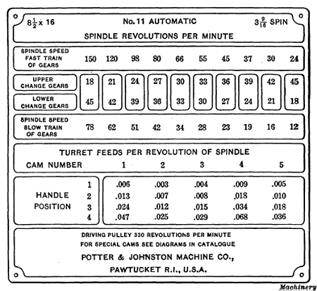
Fig. 37. Plate on the Headstock of Machine Illustrated in
Fig. 32 giving the Speeds and Feeds
Determining Speed and Feed Changes.—As previously mentioned, the particular machine illustrated in Fig. 32
can be arranged for two automatic changes of speed to suit different
diameters on the work. The change gears that will give the required
spindle speeds should first be selected. These change gears for
different speeds are listed on a speed and feed plate attached to the
headstock of the machine (see Fig. 37). It is
possible to use one speed from the list given for the fast train of
gears, and one from the list for the slow train, so long as the same
gears are not used in each case. The diameter of the collar on the work
shown in Fig. 35 is 21/2
inches, and the diameter of the body is 2 inches. Assuming that the
surface speed for this job should be about 40 feet per minute, a little
calculation shows that the 66 revolutions per minute, given by the fast
train of gears, is equivalent to a surface speed of 43 feet per minute
on a diameter of 21/2
inches. Moreover, the 78 revolutions per minute obtained from the slow
train of gearing, gives about 41 feet per minute on a diameter of 2
inches. The spindle gearing indicated for these speeds is, therefore,
placed in position on the proper studs at the back of the machine.
Next we have to determine on which faces of the turret to place the
different tools. Each turret face is numbered to agree with the
corresponding feed cam on the drum. The speed and feed plate (Fig. 37)
gives the various feeds obtainable per revolution of the spindle. As
will be seen, the different cams give different feeds. Cam No. 1 has a
coarse feed suitable for roughing; cam No. 2 a finer feed adapted to
finishing, and so on. Since the first operation consists in
rough-turning, cam No. 1 is used. Cam No. 2, which gives a finer feed,
is used for the finish-turning operation. Cam No. 4, which is ordinarily
used for reaming, could, in this case, be used for recessing, as this
recess is for clearance only and may be bored with a coarse feed.
The final operation, which is that of facing, can be done with any
cam and cam No. 5 may be used. It will be understood that for facing
operations, the feeds given do not apply. As the roll passes over the
point of the feed cam at the extreme end of the movement, the feed of
the turret slide is gradually slowed down to zero; since the facing
takes place in the last eighth or sixteenth inch of this movement, it is
done at a feed which is gradually reduced to zero. This is, of course,
as it should be, and it is not necessary to pay any attention to the
tabulated feeds in facing operations.
Setting the Turret Slide.—The next adjustment is that of
setting the turret slide. In making this adjustment the turret is set in
such relation to the work that the tools will have but a small amount
of overhang, the cam-shaft being revolved by hand until the cam-roll is
at the extreme top of the forward feeding cam, so that the turret slide
is at the extreme of its forward movement. When this adjustment has been
made by the means provided, set the turret index tripping dog so as to
revolve the turret at the proper point. After a turning tool-holder and
tool is attached to the face of the turret, cam No. 1 is placed in its
operating position and is revolved by hand until the roll is on the
point of the cam and the turret at the forward extreme of its motion. At
this point the tool-holder is set so that the cutter will be far enough
forward to complete its turning operation. The feed cam is then turned
backward, thus returning the turret slide, and the cutter is set to turn
the flange to the proper diameter for the roughing cut. The turret
slide is fed forward and back while the cutter is adjusted, and when it
is properly set, the flange is turned, the cam-drum being fed by hand.
This is the first trial cut on the piece.
A facing tool, shown in the working position in Fig. 36,
is placed at this station of the turret, being held in the turret hole.
This tool has a pilot bar and a holder which contains a facing blade.
Feeding by hand, as before, the tool is adjusted lengthwise so as to
rough-face the work to the dimension desired. In a similar way the
finish-turning and facing tools for the second position of the turret
are set, the cam-shaft being revolved by hand to bring this second face
and second cam into the working position. (The finish-facing tool is not
shown in place in Fig. 36.)
Setting the Cross-slide Cam.—As previously mentioned, the
third turret face has no tool, the cutting off of the collar being done
during this part of the cycle of operations. It has been taken for
granted that in setting the turret slide, room has been left between it
and the chuck for the cross-slide. The cross-slide is clamped in a
longitudinal position on the bed, convenient for the cutting-off
operation, which is done with a tool D (Fig. 36)
in the rear toolpost, thus leaving the front unobstructed for the
operator. When both forming and cutting off are to be done, the forming
tool is generally held at the front and the cutting-off tool at the back
because heavier and more accurate forming can be done with the work
revolving downward toward a tool in the front toolpost, than with the
tool at the rear where it is subjected to a lifting action.
Fig. 38. Diagram of Cross-slide Cams and Feeding Mechanism
The arrangement of the cross-slide cams is shown in Fig. 38, which is an end view of the large drum E, Fig. 32.
The rear feed cam is the one to be used, and since this cutting-off
operation is a short one, it may be done during the return of the turret
for position No. 3. The cam drum is, therefore, rotated by hand until
the turret face No. 3 has begun to return. The cross-slide cams are then
loosened and the rear feed cam is swung around to just touch the roller
R which operates arm A, the cross-slide having been
adjusted out to nearly the limit of its forward travel, leaving
approximately enough movement for cutting off the collar. The rear feed
cam is then clamped in this position.
A cutting-off tool is next placed in the rear toolpost at the
proper height. The rear toolpost slide is then adjusted to bring the
point of the cutting-off tool up to the work, and the cam drum is
revolved by hand until the piece is cut off. The cross-slide tool is, of
course, set in the proper position to make a collar of the required
thickness. Feeding by hand is discontinued when the roll is on the point
of the cam; the cutting-off tool slide is then permanently set on the
cross-slide so that the point of the cutting-off tool enters the bore
just far enough to completely sever the collar from the bushing. The
motion of the cam drum is continued, by hand, until the roll is over the
point of the feed cam. The cross-slide is then pushed back, by hand,
until the cam and roll are again in contact, when the return cam is
brought up and clamped in position, so that there is just room for the
roll between the feed cam and the return cam. The rear return cam (as
the hand feed of the cam drum is continued) brings the cross-slide back
to its central position. Since there is no front tool used for this
series of operations (although a tool is shown in the front toolpost, Fig. 36),
the first feed and return cams are allowed to remain wherever they
happen to be. These cam adjustments can all be made from the front of
the machine.
Fig. 39. Flexible Boring Tool used for Recessing
a Bushing in Automatic Chucking and Turning Machine
Setting the Boring Tool for Recessing.—The feeding of the
turret slide is now continued to make sure that the cutting-off tool is
returned to its normal position before the facing tool in the next face
of the turret begins to work. The facing of the bushing, so far as the
setting of the tool is concerned, is merely a repetition of the facing
operation at the first position of the turret. The recessing tool is
next set. This tool, which is shown diagrammatically in Fig. 39,
is very simple as compared with the somewhat complex operation it has
to perform. This recess is for clearance only, and accurate dimensions
and fine finish are not necessary. The recessing tool consists simply of
a slender boring-bar held in the turret and carrying a cutter suitably
located about midway the bar. The forward end of the bar is small enough
to enter a bell-mouthed bushing held in the chuck. The boring-bar is
bent to one side far enough so that the cutter clears the hole as the
bar enters, but is forced into the work as the rounded hole of the
bushing engages the end of the bar and deflects it into the working
position. The upper diagram shows the position of the bar as it enters
the hole, and the lower one the position after it has entered the
bushing and is engaged in turning the recess. This bar is set in the
turret so that at the extreme forward travel of the turret slide, the
recess will be bored to the required length. The cutter must also be
adjusted to bore to the desired diameter. This completes the setting of
the cutting tools.
Adjustments for Automatic Feed and Speed Changes.—The
machine must now be set to perform automatically the desired changes of
spindle speed and the fast and slow cam movements for the tools. After
placing a new piece of work in the machine (the first one having been
completed in the setting-up operation), the cam-shaft is revolved by
hand until the turning tool in turret face No. 1 is just about to begin
its cut. The control wheel D, Fig. 34, is
rotated in its normal direction until the next graduation marked “slow”
is in line with an index mark on the base of the machine. Then the
nearest pin M is moved up until it bears against a tooth of the
star wheel (previously referred to) and is clamped in this position. The
pin should now be in the proper location, but to test its position,
rotate the cam shaft backward by hand and throw in the automatic feed;
then watch the cut to see if the drum slows down just before the tool
begins to work. If it does not, the pin should be adjusted a little, one
way or the other, as may be required. (In going over a piece of work
for the first time, it is best to have the feed set to the smallest
rate, feed change handle K being in position No. 1.)
After the cut has been completed and the turret feed cam-roll is on
the high part of the cam, the power feed should again be stopped and
the handwheel revolved until the next graduation marked “fast” is
opposite the index mark. The next stop pin is then moved up until it
just touches the star wheel, where it is clamped in position. The feed
being again thrown in, the turret will be returned rapidly, indexed, and
moved forward for the second operation. After stopping the automatic
movement, the pins are set for this face, and so on for all the
operations, including that in which the cross-slide is used for cutting
off the finished collar.
As the first, second, and third operations are on comparatively large diameters, they should be done at the slow speed, handle J, Fig. 34,
being set to give that speed. While the turret slide is being returned
between operations 3 and 4, one of the spindle speed-changing dogs N should be clamped to the rim of disk D
so as to change the spindle speed to the fast movement. This speed is
continued until the last operation is completed, when a second dog is
clamped in place to again throw in the slow movement. The feed knock-off
dog should also be clamped in place on the disk to stop the machine at
the completion of the fifth operation, when the turret is in its rear
position. This completes the setting up of the machine. If the feed is
finer than is necessary, the feed change handle K may now be moved to a position which will give the maximum feed that can be used.
It has taken considerable time to describe the setting up of the
machine for this simple operation, but in the hands of a competent man
it can be done quite rapidly. While a simple operation has been referred
to in the foregoing, it will be understood that a great variety of work
can be done on a machine of this type. It is not unusual to see as many
as ten cutting tools operating simultaneously on a piece of work, the
tools being carried by the turret, cross-slide and back facing
attachment. The latter is operated from a separate cam applied to the
cam-shaft and acting through levers on a back facing bar which passes
through a hole in the spindle. In this back facing bar may be mounted
drills, cutters, facing tools, etc. for machining the rear face of a
casting held in the chuck jaws. Where extreme accuracy is required, a
double back facing attachment may be used, arranged with cutters for
taking both roughing and finishing cuts. The use of this attachment
often saves a second operation. This automatic chucking and turning
machine is also adapted for bar work, especially in diameters varying
from 3 to 6 inches.
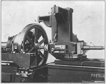
Fig. 40. Machining Flywheels in Potter & Johnston Automatic
Chucking and Turning Machine
Turning Flywheel in Automatic Chucking and Turning Machine.—A typical operation on the Potter & Johnston automatic chucking and turning machine is illustrated in Fig. 40,
which shows the machine arranged for turning the cast-iron flywheel for
the engine of a motor truck. The rim is turned and faced on both sides
and the hub is bored, reamed and faced on both sides. The flywheel
casting is held in a chuck by three special jaws which grip the inside
of the rim. The order of the operations is as follows:
The rear end of the hub is faced by the back facing bar; the cored
hole is started by a four-lipped drill in the turret and the front end
of the hub is rough-faced. (These tools are on the rear side of the
turret when the latter is in the position shown in the illustration.)
After the turret indexes, the hole is rough-bored by tool A and while this is being done, the outside of the rim is rough-turned by tool B held in a special bracket attached to the turret. Both sides of the rim are also rough-faced by tools C and D
held at the front of the cross-slide, this operation taking place at
the same time that the rim is turned and the hole is being bored.
The turret again automatically recedes and indexes, thus locating bar E and turning tool G in the working position. The hole is then finish-bored by tool E and the hub is finish-faced by blade F; at the same time the rim is finish-turned by tool G
and the sides are finish-faced to the proper width by two tools held at
the rear of the cross-slide. The turret automatically recedes and
indexes a third time, thus locating the flat-cutter reamer-bar H
in the working position and then the hole is reamed to the required
diameter. This completes the cycle of operations. The total time for
machining this flywheel is forty minutes.
Fig. 41. New Britain Multiple-spindle Automatic
Chucking Machine of Single-head Type
Automatic Multiple-spindle Chucking Machine.—An example of the specialized machines now used for producing duplicate parts, is shown in Fig. 41.
This is a “New Britain” automatic multiple-spindle chucking machine of
the single-head type and it is especially adapted for boring, reaming
and facing operations on castings or forgings which can readily be held
in chuck jaws. This particular machine has five spindles, which carry
and revolve the tools. The work being machined is held stationary in the
multiple chuck turret A which holds each part in line with one
of the spindles and automatically indexes, so that the work passes from
one spindle to another until it is finished. The turret then indexes the
finished piece to a sixth or “loading position” which is not opposite a
spindle, where the part is removed and replaced with a rough casting.
Each pair of chuck jaws is operated independently of the others by the
use of a chuck wrench. These jaws are made to suit the shape of the
work.
When a single-head machine is in operation, the turret advances and
feeds the work against the revolving tools so that a number of pieces
are operated upon at the same time. The turret is fed by a cam drum B. Cam strips are bolted to the outside of this drum and act directly against a roller attached to the yoke C which can be clamped in different positions on the spindle D, the position depending upon the length of the work. On the opposite end of the turret spindle is the indexing mechanism E. An automatically spring-operated latch F engages notches in the rim of the dividing wheel, thus accurately locating the turret. The turret is locked by a steadyrest G,
which, for each working position, automatically slides into engagement
with one of the notches in the turret. This relieves the indexing
mechanism of all strain.
This type of machine is also built with two spindle heads, the
double-head design being used for work requiring operations on both
ends. When the double-head machine is in operation, the revolving
spindles and tools advance on both sides of the chuck turret, the latter
remaining stationary except when indexing. The feed drums on the
double-head machine are located directly beneath each group of spindles.
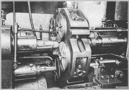
Fig. 42. Detail View of New Britain Double-head Eight-spindle
Machine, Boring, Reaming and Facing Castings
Fig. 42 shows an example of work on a
machine of the double-head design. This is an eight-spindle machine,
there being two groups of four spindles on each side of the turret. The
castings E are for the wheel hubs of automobiles. The order of
the operations on one of the castings, as it indexes around, is as
follows: The hole in the hub is first rough-reamed by taper reamer A and the opposite end of the hub is rough-faced and counterbored by a tool in spindle A1. When the turret indexes, this same casting is reamed close to the finished size by reamer B and the left end of the hub is rough-faced by cutter F, while a tool in the opposite spindle B1 finishes the counterboring and facing operation. At the third position, reamer C
finishes the hole accurately to size, and when the work is indexed to
the fourth position, the hub on the left side is finish-faced by a tool
in spindle D. (The third and fourth spindles of the right-hand
group are not used for this particular operation.) When the turret again
indexes, the finished casting is removed and replaced with a rough one.
While the successive operations on a single casting have just been
described, it will be understood that all of the tools operate
simultaneously and that a finished casting arrives at the unloading and
loading position each time the turret indexes. Three hundred of these
malleable castings are machined in nine hours.
Selecting Type of Turning Machine.—The variety of machine
tools now in use is very extensive, and as different types can often be
employed for the same kind of work, the selection of the best and most
efficient machine is often a rather difficult problem. To illustrate,
there are many different types and designs of turning machines, such as
the ordinary engine lathe, the hand-operated turret lathe, the
semi-automatic turning machine, and the fully automatic type, which,
after it is “set up” and started, is entirely independent. Hence, when a
certain part must be turned, the question is, what kind of machine
should be used, assuming that it would be possible to employ several
different machines? The answer to this question usually depends
principally upon the number of parts that must be turned.
For example, a certain casting or forging might be turned in a
lathe, which could be finished in some form of automatic or
semi-automatic turning machine much more quickly. It does not
necessarily follow, however, that the automatic is the best machine to
use, because the lathe is designed for general work and the part
referred to could doubtless be turned with the regular lathe equipment,
whereas the automatic machine would require special tools and it would
also need to be carefully adjusted. Therefore, if only a few parts were
needed, the lathe might be the best tool to use, but if a large number
were required, the automatic or semi-automatic machine would doubtless
be preferable, because the saving in time effected by the latter type
would more than offset the extra expense for tool equipment and setting
the machine. It is also necessary, in connection with some work, to
consider the degree of accuracy required, as well as the rate of
production, and it is because of these varying conditions that work of
the same general class is often done in machines of different types, in
order to secure the most efficient results.
Return to Contents