|
Turning and
Boring on a Lathe
Online Reprint Chapter 4
This a complete book, published
in 1914, divided into chapters on how to use a metal lathe,
covering all turning and boring operations.
|
Return to Contents
Turning and Boring
by Franklin D. Jones
Published by Industrial Press 1914
A special treatise for machinists students in industrial and
engineering schools, and apprentices on turning and boring methods
including modern practice with engine lathes, vertical, and horizontal
boring machines.
Shop Amazon.com
|
CHAPTER IV
THREAD CUTTING IN THE LATHE
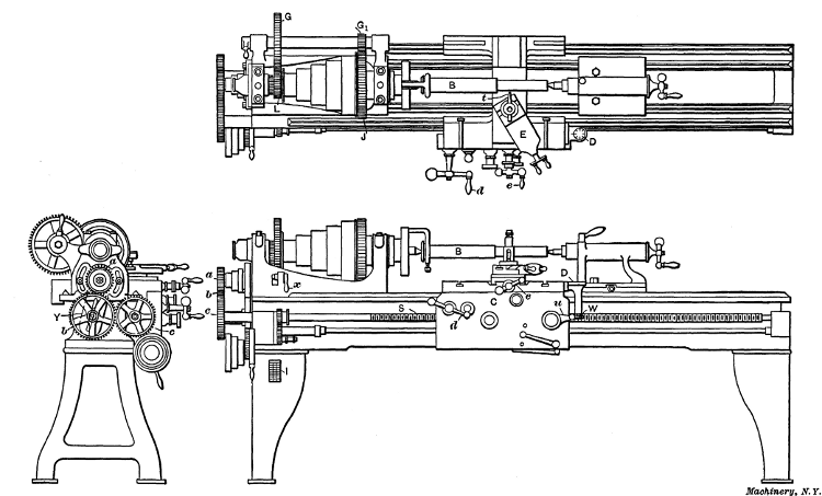
When threads are cut in the lathe a tool t is used (see Fig. 2),
having a point corresponding to the shape of the thread, and
the carriage is moved along the bed a certain distance for each
revolution of the work (the distance depending on the number
of threads to the inch being cut) by the lead-screw S which is
rotated by gears a, b and c, which receive their motion from the
spindle. As the amount that the carriage travels per revolution
of the work, and, consequently, the number of threads
per inch that is cut, depends on the size of the gears a and c
(called change gears) the latter have to be changed for cutting
different threads. The proper change gears to use for cutting
a given number of threads to the inch is ordinarily determined
by referring to a table or “index plate” I which shows what the
size of gears a and c should be, or the number of teeth each
should have, for cutting any given number of threads per inch.
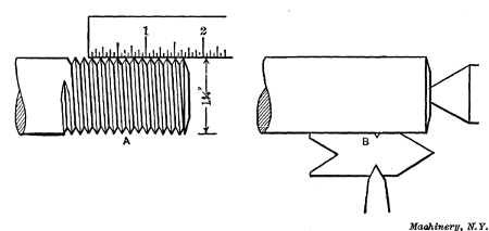
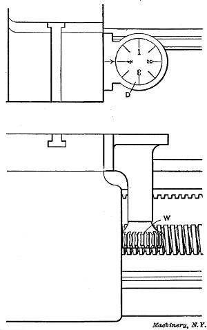
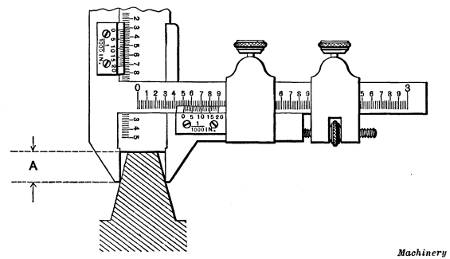
Fig. 1. Measuring Number of Threads per Inch—Setting Thread Tool
Fig. 2. Plan and Elevations of Engine Lathe
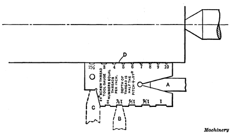
Selecting the Change Gears for Thread Cutting.—Suppose a
V-thread is to be cut on the end of the bolt B, Fig. 2, having
a diameter of 11/4 inch and seven threads per inch of length, as shown at A in Fig. 1, which is the standard number of threads
per inch for that diameter. First the change gears to use are
found on plate I which is shown enlarged in Fig. 3. This plate
has three columns: The first contains different numbers of
threads to the inch, the second the size gear to place on the
“spindle” or “stud” at a (Fig. 2) for different threads, and the
third the size of gear c for the lead-screw.
As the thread selected as
an example has 7 threads per inch,
gear a should have 48 teeth, this
being the number given in the
second column opposite figure 7
in the first. By referring to the
last column, we find that the
lead-screw gear should have 84
teeth. These gears are selected
from an assortment provided with
the lathe and they are placed on
the spindle and lead-screw, respectively.
Intermediate gear b does not
need to be changed as it is simply
an “idler” for connecting gears a
and c. Gear b is mounted on a
swinging yoke Y so that it can
be adjusted to mesh properly with
different gear combinations; after
this adjustment is made, the lathe
is geared for cutting 7 threads to
the inch. (The change gears of
many modern lathes are so arranged that different combinations
are obtained by simply shifting a lever. A lathe having this
quick-change gear mechanism is described in the latter part of
this chapter.) The work B is placed between the centers just
as it would be for turning, with the end to be threaded turned
to a diameter of 11/4 inch, which is the outside diameter of the
thread.
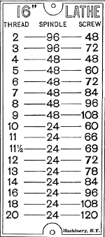
Fig. 3. Index Plate showing Gear Changes for Threading
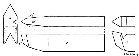
The Thread Tool.—The form of tool used for cutting a
V-thread is shown at A, Fig. 4. The end is ground V-shaped
and to an angle of 60 degrees, which corresponds to the angle of
a standard V-thread. The front or flank, f of the tool is ground
back at an angle to provide clearance, but the top is left flat or
without slope. As it is very important to grind the end to exactly
60 degrees, a gage G is used, having 60-degree notches to
which the tool-point is fitted. The tool is clamped in the toolpost
as shown in the plan view, Fig. 2, square with the work, so
that both sides of the thread will be cut to the same angle with
the axis of the work. A very convenient way to set a thread
tool square is illustrated at B, Fig. 1. The thread gage is placed
against the part to be threaded, as shown, and the tool is adjusted
until the angular sides of the point bear evenly in the
60-degree notch of the gage. The top of the tool point should
be at the same height as the lathe centers, as otherwise the
angle of the thread will not be correct.
Fig. 4. Thread Tools and Gage for testing Angle of End
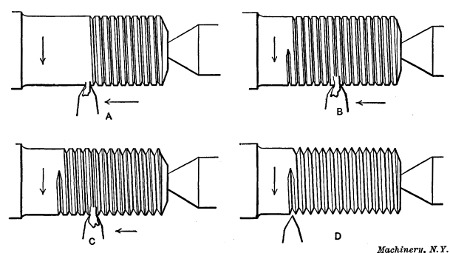
Cutting the Thread.—The lathe is now ready for cutting the
thread. This is done by taking several cuts, as indicated at A,
B, C and D in Fig. 5, the tool being fed in a little farther for
each successive cut until the thread is finished. When these
cuts are being taken, the carriage is moved along the bed, as
previously explained, by the lead-screw S, Fig. 2. The carriage
is engaged with the lead-screw by turning lever u which causes
the halves of a split nut to close around the screw. The way a lathe is
handled when cutting a thread is as follows: After the lathe is started,
the carriage is moved until the tool-point is slightly beyond the right
end of the work, and the tool is fed in far enough to take the first
cut which, ordinarily, would be about 1/16 inch deep. The carriage is then engaged with the
lead-screw, by operating lever u, and the tool moves to the left
(in this case 1/7 inch for each revolution of the work) and cuts a
winding groove as at A, Fig. 5. When the tool has traveled as
far as the thread is wanted, it is withdrawn by a quick turn of
cross-slide handle e, and the carriage is returned to the starting
point for another cut. The tool is then fed in a little farther
and a second cut is taken as at B, Fig. 5, and this operation is
repeated as at C and D until a “full” thread is cut or until the
top of the thread is sharp. The thread is then tested for size
but before referring to this part of the work, the way the carriage
is returned to the starting point after each cut should be
explained.
Fig. 5. Thread is formed by taking a Number of Successive Cuts
When the tool is withdrawn at the end of the first cut, if the
carriage is disengaged from the lead-screw and returned by
hand, the tool may or may not follow the first cut when the carriage
is again engaged with the lead-screw. If the number of
threads to the inch being cut is a multiple of the number on the
lead-screw S, then the carriage can be returned by hand and
engaged with the lead-screw at random and the tool will follow the first
cut. For example, if the lead-screw has six threads per inch, and 6,
12, 18 or any number of threads is being cut that is a multiple of six,
the carriage can be engaged at any time and the tool will always follow
the original cut. This is not the case, however, when the number of
threads being cut is not a multiple of the number on the lead-screw.
One method of bringing the carriage back to the starting point,
when cutting threads which are not multiples, is to reverse the
lathe (by shifting the overhead driving belts) in order to bring
the tool back to the starting point without disengaging the
carriage; in this way the tool is kept in the same relation to the
work, and the carriage is not disengaged from the lead-screw
until the thread is finished. This is a good method when cutting
short threads having a length of say two or three inches;
but when they are longer, and especially when the diameter is
comparatively large (which means a slower speed), it is rather
slow as considerable time is wasted while the tool is moving
back to its starting point. This is due to the fact that the
carriage is moved slowly by the lead-screw, but when disengaged,
it can be traversed quickly by turning handle d, Fig. 2.
A method of returning the carriage by hand when the number of threads
being cut is not a multiple of the number on the lead-screw is as
follows: The tool is moved a little beyond the right end of the work and
the carriage or split nut is engaged with the lead-screw. The lathe is
then turned forward by hand to take up any lost motion, and a line is
made on the lathe bed showing the position of the carriage. The
positions of the spindle and lead-screw are also marked by chalking a
tooth on both the spindle and lead-screw gears, which happens to be
opposite a corner or other point on the bed. After a cut is taken, the
carriage is returned by hand to the original starting point as shown by
the line on the bed, and is again engaged when the chalk marks show that
the spindle and lead-screw are in their original position; the tool
will then follow the first cut. If the body of the tailstock is moved
against the bridge of the carriage before starting the first cut, the
carriage can be located for each following cut by moving it back against
the tailstock, and it will not be necessary to have a line on the bed.
Fig. 6. Indicator used when Cutting Threads
Indicator or Chasing Dial for Catching Threads.—On some
lathes there is an indicator for “catching threads,” as this is
called in shop language. This is a simple device attached to
the carriage and consists
of a graduated
dial D and a worm-wheel
W (see Figs. 2
and 6) which meshes
with the lead-screw,
so that the dial is
revolved by the lead-screw
when the carriage
is stationary,
and when the carriage
is moved by the screw,
the dial remains stationary.
The indicator
is used by engaging
the carriage when
one of the graduation
lines is opposite the
arrow mark; after a
cut is taken the carriage
is returned by
hand and when one of
the graduation lines
again moves opposite
the arrow, the half-nuts are thrown into mesh, as before, and
this is repeated for each successive cut, thus causing the tool to
always come right with the thread. If the number of threads per
inch is even, engagement can be made when any line is opposite
the arrow, but for odd numbers such as 3, 7, 9, 11, etc., one of
the four long or numbered lines must be used. Of course, if the
thread being cut is a multiple of the number on the lead-screw,
engagement can be made at any time, as previously mentioned.
Principle of the Thread Indicator.—The principle upon
which the thread indicator operates is as follows: The number
of teeth in worm-wheel W is some multiple of the number of
threads per inch of the lead-screw, and the number of teeth in
the worm-wheel, divided by the pitch of the screw, equals the
number of graduations on the dial. For example, if the lead-screw
has six threads per inch, the worm-wheel could have
twenty-four teeth, in which case the dial would have four divisions,
each representing an inch of carriage travel, and by sub-dividing
the dial into eighths (as shown) each line would correspond
to 1/2 inch of travel. The dial, therefore, would enable
the carriage to be engaged with the lead-screw at points equal
to a travel of one-half inch. To illustrate the advantage of this
suppose ten threads per inch are being cut and (with the lathe
stationary) the carriage is disengaged and moved 1/6 inch or one
thread on the lead-screw; the tool point will also have moved
1/6 inch, but it will not be opposite the next thread groove in the
work as the pitch is 1/10 inch. If the carriage is moved another
thread on the lead-screw, or 2/6 inch, the tool will still be out of
line with the thread on the work, but when it has moved three
threads, or 1/2 inch, the tool will then coincide with the original
cut because it has passed over exactly five threads. This would
be true for any number of threads per inch that is divisible by
2. If the thread being cut had nine threads per inch or any
other odd number, the tool would only coincide with the thread
at points 1 inch apart. Therefore, the carriage can only be
engaged when one of the four graduations representing an inch
of travel is opposite the arrow, when cutting odd threads;
whereas even numbers can be “caught” by using any one of the
eight lines.
This indicator can also be used for “catching” fractional
threads. As an illustration, suppose 111/2
threads per inch are to be cut, and the carriage is engaged for the
first cut when graduation line 1 is opposite the arrow; engagement would
then be made for each successive cut, when either line 1 or 3 were
opposite the arrow, or in other words at spaces equal to a carriage
movement of 2 inches. As the use of the indicator when cutting
fractional threads is liable to result in error, it is better to keep
the half-nuts in engagement and return the carriage by reversing the
lathe.
Replacing Sharpened Thread Tool.—If it is necessary to
sharpen the thread tool before the thread is finished, it should
be reset square with the work by testing with the thread gage
as at B, Fig. 1. The carriage is then engaged with the lead-screw
and the lathe is turned forward to bring the tool opposite
the partly finished thread and also to take up any backlash or
lost motion in the gears or half-nut. If the tool-point is not
in line with the thread groove previously cut, it can be shifted
sidewise by feeding the compound rest E in or out, provided
the latter is set in an angular position as shown in the plan
view, Fig. 2.
If the thread tool is ground flat on the top as at A, Fig. 4, it
is not a good tool for removing metal rapidly as neither of its
two cutting edges has any slope. In order to give each cutting
edge a backward slope, it would be necessary to grind the
top surface hollow or concave, which would be impracticable.
When a course thread is to be cut, a tool shaped as at B can be
used to advantage for rough turning the thread groove, which
is afterward finished to the correct depth and angle by tool A.
This roughing tool is ground with a backward slope from the
point and the latter is rounded to make it stronger.
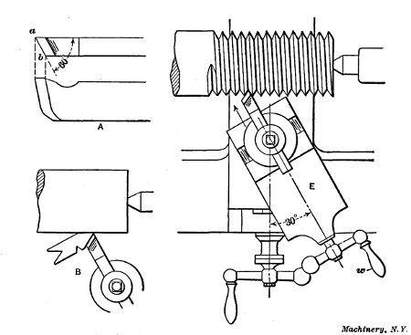
Fig. 7. Cutting Thread by using Compound Rest
Use of Compound Rest for Thread Cutting.—Another form
of thread tool is shown at A, Fig. 7, which is very good for
cutting V-threads especially of coarse pitch. When this tool is
used, the compound rest E is set to an angle of 30 degrees, as
shown, and it is fed in for the successive cuts by handle w in the
direction indicated by the arrow. It will be seen that the point
a of the tool moves at an angle of 60 degrees with the axis of
the work, thus forming one side of the thread, and the cutting
edge a—b, which can be set as shown at B, forms the
opposite side and does all the cutting. As this edge is given a backward
slope, as shown, it cuts easily and enables threading operations to be
performed quickly. Threads cut in this way are often finished by taking a
light cut with a regular thread tool. The cutting edge a—b is ground to an angle of 60 degrees (or slightly
less, if anything) with the side, as shown by sketch A.
When cutting threads in steel or wrought iron, some sort of
lubricant is usually applied to the tool to preserve the cutting
end and give a smooth finish to the thread. Lard oil or a mixture
of equal parts of lard oil and paraffin oil are often used for this
purpose. If the thread is small, the lubricant may be applied
from an ordinary oil can, but when cutting comparatively large
threads, it is better to have a stream of oil constantly playing
upon the tool-point. This constant flow may be obtained by
mounting a can having a spout leading to the tool, on a bracket
at the rear of the carriage.
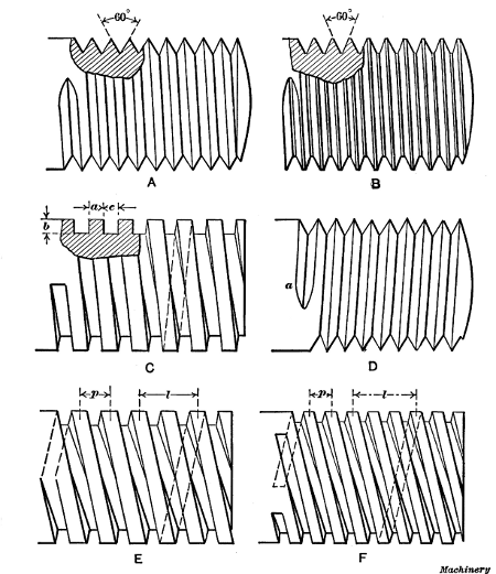
Fig. 8. (A) V-thread.
(B) U. S. Standard Thread.
(C) Square Thread.
(D)
Left-hand Thread.
(E) Double Square Thread.
(F) Triple Square Thread
Threads Commonly Used.—Three forms of threads or screws
which are in common use are shown in Fig. 8; these are the
V-thread (A), the U. S. standard (B), and the square thread
(C). The shapes of these threads are shown by the sectioned
parts. The V-thread has straight sides which incline at an angle of 60
degrees with each other and at the same angle with the axis of the
screw. The U. S. standard thread is similar to the V-thread except that
the top of the thread and bottom of the groove is left flat, as shown,
and the width of these flats is made equal to 1/8 of the pitch. The square thread is square in
section, the width a, depth b and space c being all
equal. All of these threads are right-hand, which means that the
grooves wind around to the right so that a nut will have to be turned
toward the right to enter it on the thread. A left-hand thread winds in
the other direction, as shown at D, and a nut is screwed
on by turning it to the left.
Multiple Threads.—Threads, in addition to being right-and
left-handed, are single, as at A, B, C and D, double, as at E,
and triple, as at F, and for certain purposes quadruple threads
or those of a higher multiple are employed. A double thread
is different from a single thread in that it has two grooves,
starting diametrically opposite, whereas a triple thread has three
grooves cut as shown at F. The object of these multiple
threads is to obtain an increase in lead without weakening the
screw. For example, the threads shown at C and E have the
same pitch p but the lead l of the double-threaded screw is
twice that of the one with a single thread so that a nut would
advance twice as far in one revolution, which is often a very
desirable feature. To obtain the same lead with a single thread,
the pitch would have to be double, thus giving a much coarser
thread, which would weaken the screw, unless its diameter
were increased. (The lead is the distance l that one thread advances
in a single turn, or the distance that a nut would advance
in one turn, and it should not be confused with the pitch p,
which is the distance between the centers of adjacent threads.
Obviously the lead and pitch of a single thread are the same.)
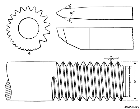
Fig. 9. U. S. Standard Thread, Thread Tool, and Gage
Cutting a U. S. Standard Thread.—The method of cutting a
U. S. standard thread is the same as described for a V-thread,
so far as handling the lathe is concerned. The thread tool
must correspond, of course, to the shape of a U. S. standard
thread. This tool is first ground to an angle of 60 degrees, as
it would be for cutting a V-thread, and then the point is made
flat as shown in Fig. 9. As will be recalled, the width of this
flat should be equal to 1/8 of the pitch. By using a gage like the
one shown at G, the tool can easily be ground for any pitch, as
the notches around the periphery of the gage are marked for
different pitches and the tool-point is fitted into the notch corresponding
to the pitch wanted. If such a gage is not available, the
width of the flat at the point can be tested by using, as a gage,
a U. S. standard tap of the same pitch as the thread to be cut.
When cutting the thread, the tool is set square with the blank, and a
number of successive cuts are taken, the tool being fed in until the
width w of the flat at the top of the thread is equal to the width at
the bottom. The thread will then be the right size provided the outside
diameter D is correct and the tool is
of the correct form. As it would be difficult to measure the
width of this flat accurately, the thread can be tested by screwing
a standard nut over it if a standard thread is being cut. If
it is being fitted to a tapped hole, the tap itself is a very convenient
gage to use, the method being to caliper the tap and
then compare its size with the work.
A good method of cutting a U. S. standard thread to a given
size is as follows: First turn the outside of the blank accurately
to diameter D, and then turn a small part of the end to diameter
r of the thread at the root. The finishing cut for the thread
is then taken with the tool point set to just graze diameter r.
If ordinary calipers were set to diameter r and measurements
taken in the thread groove, the size would be incorrect owing to the
angularity of the groove, which makes it necessary to hold the calipers
at an angle when measuring. To determine the root diameter divide 1.299
by the number of threads per inch and subtract the quotient from the
outside diameter. Expressing this rule as a formula,
in which D equals outside diameter; N, the number of threads
per inch; and r, the root diameter. The number 1.299 is a constant
that is always used.
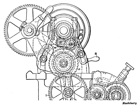
Fig. 10. End View of Lathe Headstock
Cutting a Left-hand Thread.—The only difference between
cutting left-hand and right-hand threads in the lathe is in the
movement of the tool with relation to the work. When cutting
a right-hand thread, the tool moves from right to left, but this
movement is reversed for left-hand threads because the thread
winds around in the opposite direction. To make the carriage
travel from left to right, the lead-screw is rotated backwards
by means of reversing gears a and b (Fig. 10) located in the headstock. Either of these gears can be engaged with the spindle gear by changing the position of lever R. When gear a
is in engagement, as shown, the drive from the spindle to gear
c is through gears a and b, but when lever R is raised thus shifting
b into mesh, the drive is direct and the direction of rotation
is reversed. The thread is cut by starting the tool at a, Fig. 8,
instead of at the end.
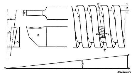
Fig. 11. End of Square Thread Tool, and Graphic Method of
Determining Helix Angle of Thread
Cutting a Square Thread.—The form of tool used for cutting
a square thread is shown in Fig. 11. The width w is made
equal to one-half the pitch of the thread to be cut and the end E
is at an angle with the shank, which corresponds to the inclination
x—y of the threads. This angle A depends upon the
diameter of the screw and the lead of the thread; it can be determined
graphically by drawing a line a—b equal in length to
the circumference of the screw to be cut, and a line b—c, at right
angles, equal in length to the lead of the thread. The angle α
between lines a—b and a—c will be the required angle A. (See
end view of thread tool). It is not necessary to have this angle
accurate, ordinarily, as it is simply to prevent the tool from
binding against the sides of the thread. The end of a square
thread tool is shown in section to the right, to illustrate its
position with relation to the threads. The sides e and e1 are
ground to slope inward, as shown, to provide additional clearance.
When cutting multiple threads, which, owing to their increased lead,
incline considerably with the axis of the screw, the angles for each
side of the tool can be determined independently as follows: Draw line a—b equal in length to the circumference
of the thread, as before, to obtain the required
angle f of the rear or following side e1; the angle l of the opposite
or leading side is found by making a—b equal to the circumference
at the root of the thread. The tool illustrated is for
cutting right-hand threads; if it were intended for a left-hand
thread, the end, of course, would incline in the opposite direction.
The square thread is cut so that the depth d is equal to
the width. When threading a nut for a square thread screw, it
is the usual practice to use a tool having a width slightly greater
than one-half the pitch, to provide clearance for the screw, and
the width of a tool for threading square-thread taps to be used
for tapping nuts is made slightly less than one-half the pitch.
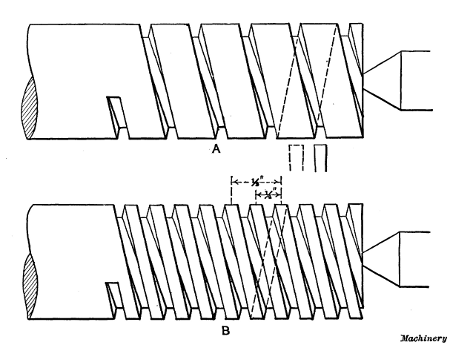
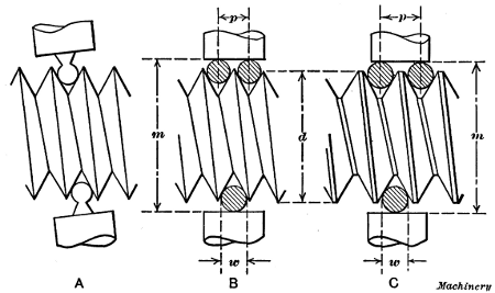
Fig. 12. Views illustrating how a Double Square Thread is Cut
Cutting Multiple Threads.—When a multiple thread is to be
cut, such as a double or triple thread, the lathe is geared with
reference to the number of single threads to the inch. For example,
the lead of the double thread, shown at B, Fig. 12, is
one-half inch, or twice the pitch, and the number of single
threads to the inch equals 1 ÷ 1/2 = 2. Therefore, the lathe is
geared for cutting two threads per inch. The first cut is taken
just as though a single thread were being cut, leaving the work
as shown at A. When this cut is finished the work is turned
one-half a revolution (for a double thread) without disturbing
the position of the lead-screw or carriage, which brings the tool
midway between the grooves of the single thread as indicated
by dotted lines. The second groove is then cut, producing a
double thread as shown at B. In the case of a triple thread,
the work would be indexed one-third of a revolution after turning
the first groove, and then another third revolution to locate
the tool for cutting the last groove. Similarly, for a quadruple
thread, it would be turned one-quarter revolution after cutting
each successive groove or thread.
There are different methods of indexing the work when cutting
multiple threads, in order to locate the tool in the proper position for
cutting another thread groove. Some machinists, when cutting a double
thread, simply remove the work from the lathe and turn it one-half a
revolution by placing the tail of the driving dog in the opposite slot
of the faceplate. This is a very simple method, but if the slots are not
directly opposite or 180 degrees apart, the last thread will not be
central with the first. Another and better method is to disengage the
idler gear from the gear on the stud, turn the spindle and work
one-half, or one-third, of a revolution, as the case might be, and then
connect the gears. For example, if the stud gear had 96 teeth, the tooth
meshing with the idler gear would be marked with chalk, the gears
disengaged, and the spindle turned until the chalked tooth had made the
required part of a revolution, which could be determined by counting the
teeth. When this method is used, the number of teeth in the stud gear
must be evenly divisible by two if a double thread is being cut, or by
three for a triple thread, etc. If the stud is not geared to the spindle
so that each makes the same number of revolutions, the ratio of the
gearing must be considered.
Setting Tool When Cutting Multiple Threads.—Another
method, which can sometimes be used for setting the tool after
cutting the first groove of a multiple thread, is to disengage the
lock-nuts from the lead-screw (while the spindle is stationary)
and move the carriage back whatever distance is required to
locate the tool in the proper position for taking the second cut.
Evidently this distance must not only locate the tool in the right
place, but be such that the lock-nuts can be re-engaged with
the lead-screw. Beginning with a simple illustration, suppose a
double thread is being cut having a lead of 1 inch. After the
first thread groove is cut, the tool can be set in a central position
for taking the second cut, by simply moving the carriage back
1/2 inch (one-half the lead), or 1/2 inch plus the lead or any
multiple of the lead. If the length of the threaded part were
5 inches, the tool would be moved back far enough to clear the
end of the work, or say 1/2 + 5 = 51/2 inches. In order to disengage
the lock-nuts and re-engage them after moving the carriage
51/2 inches (or any distance equal, in this case, to one-half
plus a whole number), the lead-screw must have an even number
of threads per inch.
Assume that a double thread is being cut having 11/4 single
threads per inch. The lead then would equal 1 ÷ 11/4 = 0.8
inch, and if the carriage is moved back 0.8 ÷ 2 = 0.4 inch, the
tool will be properly located for the second cut; but the lock-nuts
could not be re-engaged unless the lead-screw had ten
threads per inch, which is finer than the pitch found on the
lead-screws of ordinary engine lathes. However, if the movement
were 0.4 + 0.8 × 2 = 2 inches, the lock-nuts could be re-engaged
regardless of the number of threads per inch on the
lead-screw. The rule then, is as follows:
Divide the lead of the thread by 2 for a double thread, 3 for a
triple thread, 4 for a quadruple thread, etc., thus obtaining the
pitch; then add the pitch to any multiple of the lead, which will
give a movement, in inches, that will enable the lock-nuts to be re-engaged
with the lead-screw.
Whenever the number obtained by this rule is a whole number,
obviously, the movement can be obtained with a lead-screw of any pitch.
If the number is fractional, the number of threads per inch on the
lead-screw must be divisible by the denominator of the fraction.
To illustrate the application of the foregoing rule, suppose a
quadruple thread is to be cut having 11/2 single threads per inch
(which would be the number the lathe would be geared to cut).
Then the lead of the thread = 1 ÷ 11/2 = 0.6666 inch and the
pitch = 0.6666 ÷ 4 = 0.1666 inch; adding the pitch to twice
the lead we have 0.1666 + 2 × 0.6666 = 1.499 inch. Hence, if
the carriage is moved 11/2 inch (which will require a lead-screw
having an even number of threads per inch), the tool will be
located accurately enough for practical purposes. When the
tool is set in this way, if it does not clear the end of the part
being threaded, the lathe can be turned backward to place the
tool in the proper position.
The foregoing rule, as applied to triple threads or those of a
higher number, does not always give the only distance that the
carriage can be moved. To illustrate, in the preceding example
the carriage movement could be equal to 0.499, or what is practically
one-half inch, instead of 11/2 inch, and the tool would be
properly located. The rule, however, has the merit of simplicity
and can be used in most cases.
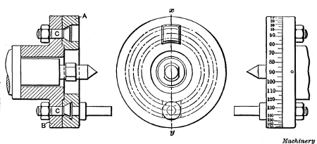
Fig. 13. Indexing Faceplate used for Multiple Thread Cutting
Special faceplates are sometimes used for multiple thread
cutting, that enable work to be easily and accurately indexed.
One of these is illustrated in Fig. 13; it consists of two parts Aand B, part A being free to rotate in relation to B when bolts C
are loosened. The driving pin for the lathe dog is attached to
plate A. When one groove of a multiple thread is finished,
bolts C are loosened and plate A is turned around an amount
corresponding to the type of thread being cut. The periphery
of plate A is graduated in degrees, as shown, and for a double
thread it would be turned one-half revolution or 180 degrees,
for a triple thread, 120 degrees, etc. This is a very good arrangement
where multiple thread cutting is done frequently.
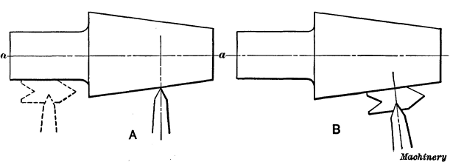
Fig. 14. Correct and Incorrect Positions of Tool for Taper Thread Cutting
Taper Threading.—When a taper thread is to be cut, the
tool should be set square with axis a—a as at A, Fig. 14, and
not by the tapering surface as at B. If there is a cylindrical
part, the tool can be set as indicated by the dotted lines. All
taper threads should be cut by the use of taper attachments.
If the tailstock is set over to get the required taper, and an
ordinary bent-tail dog is used for driving, the curve of the
thread will not be true, or in other words the thread will not
advance at a uniform rate; this is referred to by machinists as
a “drunken thread.” This error in the thread is due to the
angularity between the driving dog and the faceplate, which
causes the work to be rotated at a varying velocity. The pitch
of a taper thread that is cut with the tailstock set over will also
be slightly finer than the pitch for which the lathe is geared.
The amount of these errors depends upon the angle of the taper
and the distance that the center must be offset.
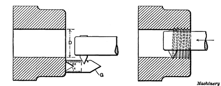
Fig. 15. Method of setting and using Inside Thread Tool
Internal Threading.—Internal
threading, or cutting threads in holes, is an operation performed on
work held in the chuck or on a faceplate, as for boring. The tool used
is similar to a boring tool except that the working end is shaped to
conform to the thread to be cut. The method of procedure, when cutting
an internal thread, is similar to that for outside work, as far as
handling the lathe is concerned. The hole to be threaded is first bored
to the root diameter D, Fig. 15, of the screw that is
to fit into it. The tool-point (of a tool for a U. S. standard or
V-thread) is then set square by holding a gage G against the
true side of the work and adjusting the point to fit the notch in
the gage as shown. The view to the right shows the tool taking
the first cut.
Very often the size of a threaded hole can be tested by using
as a gage the threaded part that is to fit into it. When making
such a test, the tool is, of course, moved back out of the way.
It is rather difficult to cut an accurate thread in a small hole,
especially when the hole is quite deep, owing to the flexibility
of the tool; for this reason threads are sometimes cut slightly
under size with the tool, after which a tap with its shank end
held straight by the tailstock center is run through the hole.
In such a case, the tap should be calipered and the thread made
just small enough with the tool to give the tap a light cut.
Small square-threaded holes are often finished in this way, and
if a number of pieces are to be threaded, the use of a tap makes
the holes uniform in size.
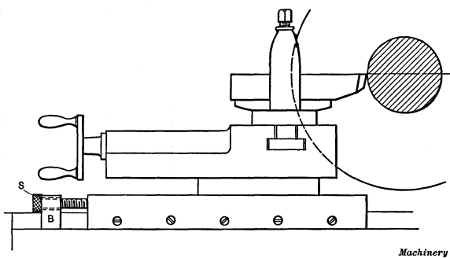
Fig. 16. Cross-slide equipped with Stop for Regulating Depth
of Cut when Threading
Stop for Thread Tools.—When
cutting a thread, it is rather difficult to feed in the tool just the
right amount for each successive cut, because the tool is moved in
before it feeds up to the work. A stop is sometimes used for threading which overcomes this difficulty. This stop consists of a screw S, Fig. 16,
which enters the tool slide and passes through a block B clamped
in front of the slide. The hole in the block through which the
stop-screw passes is not threaded, but is large enough to permit
the screw to move freely. When cutting a thread, the tool is
set for the first cut and the screw is adjusted until the head is
against the fixed block. After taking the first cut, the stop-screw
is backed out, say one-half revolution, which allows the
tool to be fed in far enough for a second cut. If this cut is
about right for depth, the screw is again turned about one-half
revolution for the next cut and this is continued for each successive
cut until the thread is finished. By using a stop of this
kind, there is no danger of feeding the tool in too far as is often
done when the tool is set by guess. If this form of stop is used
for internal threading, the screw, instead of passing through the
fixed block, is placed in the slide so that the end or head will
come against the stop B. This change is made because the tool
is fed outward when cutting an internal thread.
Fig. 17. Gage for grinding and setting Acme Thread Tools
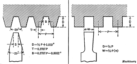
The Acme Standard Thread.—The Acme thread is often
used, at the present time, in place of a square thread. The
angle between the sides of the Acme thread is 29 degrees (see
Fig. 21) and the depth is made equal to one-half
the pitch plus 0.010 inch to provide clearance and insure a bearing
upon the sides. The thread tool is ordinarily ground to fit a gage
having notches representing different pitches. An improved form of Acme
thread gage is shown in Fig. 17. The tool point is first
ground to the correct angle by fitting it to the 29-degree notch
in the end of the gage, as at A. The end is then ground to the
proper width for the pitch to be cut, by testing it, as at B. The
numbers opposite the shallow notches for gaging the width represent
the number of threads per inch. With this particular gage,
the tool can be set square by placing edge D against the turned
surface to be threaded, and adjusting the tool until the end is in
line with the gage, as at C. By placing the tool in this position,
the angle between the side and the end can also be tested.
Fig. 18. Measuring Width of Acme Thread Tool with Vernier Gear-tooth
Caliper
In case it should be necessary to measure the end width of
an Acme thread tool, for a pitch not on the regular gage, this
can be done by using a vernier gear-tooth caliper, as indicated
in Fig. 18. If we assume that the caliper jaws bear on the sides
of the tool at a distance A from the top, equal to 1/4
inch, then the width of the tool point equals the caliper reading (as
shown by the horizontal scale) minus 0.1293 inch. For example, if the
caliper reading was 0.315 inch, the width at the point would equal 0.315
- 0.1293 = 0.1857 inch, assuming that the sides were ground to the
standard angle of 29 degrees. The constant to be subtracted from the
caliper reading equals 2 A tan 14° 30'
or, in this case, 2 × 0.25 × 0.2586 = 0.1293.
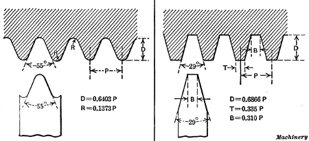
The Whitworth Thread.—The Whitworth (or British Standard
Whitworth) thread, which is used principally in Great
Britain, has an included angle of 55 degrees, and the threads
are rounded at the top and at the root, as shown in Fig. 23.
The shape of the tool used for cutting this thread is also shown
in this illustration. The end is rounded to form the fillet at
the root of the thread, and the round corners on the sides give
the top of the thread the required curvature. Every pitch requires
a different tool, and the cutting end is given the curved
form by milling or hobbing. The hob used for this purpose is
accurately threaded to correspond with the pitch for which
the tool is required, and then it is fluted to form cutting edges,
and is hardened. The hob is then used like a milling cutter
for forming the end of the thread tool. The tool is sharpened
by grinding on the top. The method of cutting a Whitworth
thread is, of course, similar to that followed for a U. S. standard
or V-thread, in that the tool is set square with the unthreaded
blank and at the same height as the lathe centers, in order to
secure a thread of the proper form. Care should be taken to
turn the blank to the right diameter so that the top of the
thread will be fully rounded when the screw is the required size.
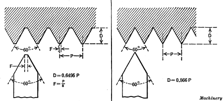
Fig. 19. United States Standard Thread
Fig. 20. Standard Sharp V-thread
Fig. 21. Acme Standard Thread
Fig. 22. Square Thread
Fig. 23. Whitworth Standard Thread
Fig. 24. Standard Worm Thread
Worm Threads.—The standard worm thread has an angle
of 29 degrees between the sides, the same as an Acme thread,
but the depth of a worm thread and the width of the flat at the
top and bottom differ from the Acme standard, as will be seen
by comparing Figs. 21 and 24. The whole depth of the thread
equals the linear pitch multiplied by 0.6866, and the width of
the thread tool at the end equals the linear pitch multiplied by
0.31. Gages notched for threads of different pitch are ordinarily
used when grinding worm thread tools.
When it is necessary to cut multiple-threaded worms of large
lead in an ordinary lathe, difficulty is sometimes experienced
because the lead-screw must be geared to run much faster than
the spindle, thus imposing excessive strains on the gearing.
This difficulty is sometimes overcome by mounting a belt pulley
on the lead-screw, beside the change gear, and connecting
it to the countershaft by a belt; the spindle is then driven
through the change gearing from the lead-screw, instead of vice
versa.
Coarse Threading Attachment.—To avoid the difficulties
connected with cutting threads of large lead, some lathes are
equipped with a coarse screw-cutting attachment. The arrangement
of this attachment, as made by the Bradford Machine
Tool Co., is as follows: On the usual reversing shaft, and inside
of the headstock, there is a sliding double gear, so arranged as
to be engaged with either the usual gear on the spindle, or with
a small pinion at the end of the cone. The gears are so proportioned
that the ratio of the two engagements is as 10 to 1;
that is, when engaged with the cone gear (the back-gears being
thrown in) the mating gear will make ten revolutions to one of
the spindle, so that when the lathe is ordinarily geared to cut
one thread per inch, it will, when driven by the cone pinion,
cut one thread in ten inches. This construction dispenses with
the extra strain on the reverse gears due to moving the carriage
at the rapid rate that would be necessary for such a large
lead, when not using an attachment. These attachments are
not only extensively used for the cutting of coarse screws but
for cutting oil grooves on cylindrical parts.
When cutting a thread
of large lead or “steep pitch,” the top
of the thread tool should be ground so that it is at right angles
to the thread; then the thread groove will be cut to the same
width as the tool.
Testing the Size of a Thread.—When the thread tool has
been fed in far enough to form a complete thread, the screw is
then tested for size. If we assume that a bolt is being threaded
for a standard nut, it would be removed from the lathe and the
test made by screwing a nut on the end. If the thread were
too large, the nut might screw on very tightly or not at all; in
either case, the work would again be placed in the lathe and a
light cut taken over it to reduce the thread to the proper size.
When replacing a threaded part between the centers, it should
be put back in the original position, that is, with the “tail” of
the driving dog in the same slot of the faceplate it previously
occupied.
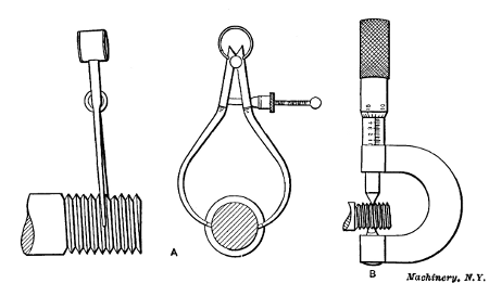
Fig. 25. Testing Diameter of Thread with Calipers and Micrometer
As it is difficult to tell just when a thread is cut to the exact
size, special thread calipers having wedge-shaped ends are
sometimes used for measuring the diameter of a V-thread or a
U. S. standard thread, at the bottom of the grooves or the root
diameter, as shown at A in Fig. 25. These calipers can be set
from a tap corresponding to the size of the thread being cut, or
from a previously threaded piece of the right size.
The Thread Micrometer.—Another form of caliper for testing
threads is shown at B. This is one of the micrometer type
and is intended for very accurate work. The spindle of this
micrometer has a conical end and the “anvil” is V-shaped,
and these ends bear on the sides of the thread or the surfaces
which form the bearing when the screw is inserted in a nut or
threaded hole. The cone-shaped point is slightly rounded so
that it will not bear in the bottom of the thread. There is also
sufficient clearance at the bottom of the V-shaped anvil to prevent
it from bearing on top of the thread. The diameter as
indicated by this micrometer is the “pitch diameter” of the
thread and is equal to the outside diameter minus the depth of
one thread. This depth may be determined as follows:
Depth of a V-thread = 0.866 ÷ No. of threads per inch;
Depth of a U. S. standard thread = 0.6495 ÷ No. of threads
per inch;
Depth of Whitworth thread = 0.6403 ÷ No. of threads per inch.
The movable point measures all pitches, but the fixed anvil
is limited in its capacity, for if made large enough to measure a
thread of, say, 1/4-inch pitch, it would be too wide at the top to
measure a thread of 1/24-inch pitch, hence each caliper is limited
in the range of threads that the anvil can measure. When
measuring the “angle diameter” of a thread, the micrometer
should be passed back and forth across the thread, in order to
make sure that the largest dimension or the actual diameter is
being measured. If the micrometer is placed over what seems
to be the center of the screw and the reading is taken by simply
adjusting in the anvil or point against the thread, without moving
the micrometer back and forth across it, an incorrect reading
may be obtained.
Fig. 26. (A) Testing Size of Thread with Ball-point Micrometer.
(B) Testing Size
of V-thread by the Three-wire System.
(C) Testing the Size of a U. S. Standard Thread
If standard threaded reference gages are available, the size
of the thread being cut can be tested by comparing it with the
gage. Micrometers having small spherical measuring ends (see
sketch A, Fig. 26) are sometimes used for this purpose. The
ball points are small enough to bear against the sides of the
thread and the diameter, as compared with the reference gage,
can be determined with great accuracy.
Three-wire System of Measuring Threads.—A method of
measuring threads by using an ordinary micrometer and three
wires of equal diameter is illustrated at B and C, Fig. 26. Two
wires are placed between the threads on one side and one on the
opposite side of the screw. The dimension M over the wires is
then measured with an ordinary micrometer. When the thread
is cut to a standard size, the dimension M for different threads
is as follows:
For a U. S. standard thread:
m = d - 1.5155p + 3w
For a sharp V-thread:
m = d - 1.732p + 3w
For a Whitworth standard thread:
m = d - 1.6008p + 3.1657w
In these formulas, d = standard outside diameter of screw;
m = measurement over wires; w = diameter of wires; p =
pitch of thread = 1 ÷ number of threads per inch.
To illustrate the use of the formula for the U. S. standard
thread, let us assume that a screw having 6 threads per inch
(1/6-inch pitch) is to be cut to a diameter of 11/2
inch, and that wires 0.140 inch diameter are to be used in conjunction
with a micrometer for measurement. Then the micrometer reading m should
be
11/2 - 1.5155 × 1/6 + 3 × 0.140 = 1.6674 inch
If the micrometer reading were 1.670 inch, it would indicate
that the pitch diameter of the screw was too large, the error
being equal to difference between 1.667 and the actual reading.
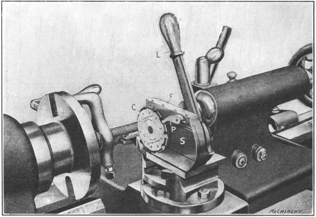
Fig. 27. Rivett-Dock Circular Threading Tool in Working Position
Rivett-Dock Threading Tool.—A special form of thread tool,
which overcomes a number of disadvantages common to an
ordinary single-point thread tool, is shown in Fig. 27. This
tool has a circular-shaped cutter C, having ten teeth around its
circumference, which, beginning with tooth No. 1, gradually increase
in height, cutter No. 2 being higher than No. 1, etc.
This cutter is mounted on a slide S, that is fitted to the frame
F, and can be moved in or out by lever L. The hub of this lever
has an eccentric stud which moves slide S and locks it when
in the forward or cutting position. The action of the lever in
moving the slide engages the cutter with pawl P, thus rotating
the cutter one tooth at a time and presenting a different tooth to the
work for each movement of the lever. When the slide is moved forward,
the heel or underside of the tooth which is in the working position
rests on a stop that takes the thrust of the cut.
When the tool is in use, it is mounted on the tool-block of the
lathe as shown in the illustration. The cutter is set for height
by placing a tooth in the working position and setting the top
level with the lathe center. The cutter is also set square with
the work by using an ordinary square, and it is tilted slightly
from the vertical to correspond with the angle of the thread to
be cut, by adjusting frame F. At first a light cut is taken with
lever L moved forward and tooth No. 1 on the stop. After
this cut is completed, the lever is reversed which rotates the
cutter one tooth, and the return movement places tooth No. 2
in the working position. This operation is repeated until the
tenth tooth finishes the thread. It is often necessary, when
using a single-point thread tool, to re-sharpen it before taking
the finishing cut, but with a circular tool this is not necessary,
for by using the different teeth successively, the last tooth,
which only takes finishing cuts, is kept in good condition.
Cutting Screws to Compensate for Shrinkage.—Some tool
steels are liable to shrink more or less when they are hardened;
consequently if a very accurate hardened screw is required, it is
sometimes cut so that the pitch is slightly greater than standard,
to compensate for the shrinkage due to the hardening
operation. As the amount of contraction incident to hardening
is very little, it is not practicable to use change gears that will
give the exact pitch required. A well-known method of obtaining
this increase of pitch is by the use of a taper attachment.
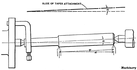
Fig. 28. Diagram Illustrating Method of Cutting a Thread to
Compensate for the Error in Pitch
due to Shrinkage in Hardening
For example, suppose a tap having 8 threads per inch is to be
threaded, and, owing to the contraction of the steel, the pitch
must be 0.12502 inch instead of 0.125 inch. The lathe is geared
to cut 8 threads per inch or 0.125 inch pitch, and then the
taper attachment is set to an angle a, Fig. 28, the cosine of
which equals 0.125÷0.12502; that is, the cosine of angle a equals the
pitch required after hardening, divided by the pitch necessary to
compensate for shrinkage. The angle is then found by referring to a
table of cosines. The tap blank is also set to the same angle a by
adjusting the tailstock center, thus locating the axis of the work
parallel with the slide of the taper attachment. When the carriage moves
a distance x, the tool point will have
moved a greater distance y along the work, the difference between
x and y depending upon angle a; hence the tool will cut
a thread of slightly greater pitch than the lathe is geared to cut.
To illustrate by using the preceding example, cosine of angle
a = 0.125÷0.12502 = 0.99984. By referring to a table of cosines, we
find that 0.99984 is the cosine of 1 degree, approximately;
hence, the taper attachment slide and the work should be set
to this angle. (The angle a in Fig. 28 has been exaggerated in
order to more clearly illustrate the principle.)
As is well known, it is objectionable to cut a thread with the
tailstock center offset, because the work is not rotated at a
uniform velocity, owing to the fact that the driving dog is at an
angle with the faceplate. For a small angle such as 1 degree,
however, the error resulting from this cause would be very
small.
If a thread having a pitch slightly less than standard is needed to
fit a threaded part which has contracted in hardening, the taper
attachment can also be used provided the lathe is equipped with special
gears to cut a little less than the required pitch. Suppose a screw
having a pitch of 0.198 inch is required to fit the thread of a nut the
pitch of which has been reduced from 0.200 inch to 0.198 inch. If gears
having 83 and 84 teeth are available, these can be inserted in a
compound train, so as to reduce the 0.200 inch pitch that would be
obtained with the regular gearing, to 83/84 of 0.200 or 0.19762 inch.
This pitch, which is less than the 0.198 inch pitch required, is
then increased by using the taper attachment as previously described.
(This method was described by Mr. G. H. Gardner
in Machinery, February, 1914.)
Calculating Change Gears for Thread Cutting.—As previously
mentioned, the change gears for cutting threads of various
pitches are shown by a table or “index plate” attached to
the lathe. The proper gears to be used can be calculated, but
the use of the table saves time and tends to avoid mistakes.
Every machinist, however, should know how to determine the
size of gears used for cutting any number of threads to the
inch. Before referring to any rules, let us first consider why a
lathe cuts a certain number of threads to the inch and how this
number is changed by the use of different gears.
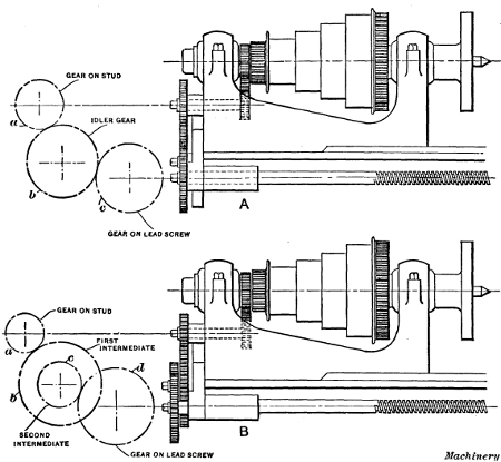
Fig. 29. (A) Lathe with Simple Gearing for Thread Cutting.
(B) Compound Geared Lathe
As the carriage C and the tool are moved by the lead-screw
S (see Fig. 2), which is geared to the spindle, the number of
threads to the inch that are cut depends, in every case, upon the
number of turns the work makes while the lead-screw is moving
the carriage one inch. If the lead-screw has six threads per
inch, it will make six revolutions while the carriage and the
thread tool travel one inch along the piece to be threaded.
Now if the change gears a and c (see also sketch A, Fig. 29) are
so proportioned that the spindle makes the same number of
revolutions as the lead-screw, in a given time, it is evident that
the tool will cut six threads per inch. If the spindle revolved
twice as fast as the lead-screw, it would make twelve turns
while the tool moved one inch, and, consequently, twelve threads
per inch would be cut; but to get this difference in speeds it is
necessary to use a combination of gearing that will cause the
lead-screw to revolve once while the lathe spindle and work
make two revolutions.
Suppose that nine threads to the inch are to be cut and the
lead-screw has six threads per inch. In this case the work must
make nine revolutions while the lead-screw makes six and causes
the carriage and thread tool to move one inch, or in other words,
one revolution of the lead-screw corresponds to one and one-half
revolution of the spindle; therefore, if the lead-screw gear
c has 36 teeth, the gear a on the spindle stud should have
24 teeth. The spindle will then revolve one and one-half times faster
than the lead-screw, provided the stud rotates at the same rate of speed
as the main lathe spindle. The number of teeth in the change gears that
is required for a certain pitch can be found by multiplying the number
of threads per inch of the lead-screw, and the number of threads per
inch to be cut, by the same trial multiplier. The formula which
expresses the relation between threads per inch of lead-screw, threads
per inch to be cut, and the number of teeth in the change gears, is as
follows:
Applying this to the example given, we have 6÷9 = 24÷36. The
values of 36 and 24 are obtained by multiplying 6 and 9, respectively,
by 4, which, of course, does not change the proportion.
Any other number could be used as a multiplier, and if gears
having 24 and 36 teeth were not available, this might be necessary.
For example, if there were no gears of this size, some
other multiplier as 5 or 6 might be used.
Suppose the number of teeth in the change gears supplied
with the lathe are 24, 28, 32, 36, etc., increasing by four teeth
up to 100, and assume that the lead-screw has 6 threads per
inch and that 10 threads per inch are to be cut. Then,
By multiplying both numerator and denominator by 4, we
obtain two available gears having 24 and 40 teeth, respectively.
The 24-tooth gear goes on the spindle stud and, the 40-tooth gear
on the lead-screw. The number of teeth in the intermediate or
“idler” gear b, which connects the stud and lead-screw gears, is
not considered as it does not affect the ratios between gears a
and c, but is used simply to transmit motion from one gear to
the other.
We have assumed in the foregoing that the spindle stud (on
which gear a is mounted) and the main spindle of the lathe are
geared in the ratio of one to one and make the same number of
revolutions. In some lathes, however, these two members do not rotate at
the same speed, so that if equal gears were placed on the lead-screw
and spindle stud, the spindle would not make the same number of
revolutions as the lead-screw. In that case if the actual number of
threads per inch in the lead-screw were used when calculating the change
gears, the result would be incorrect; hence, to avoid mistakes, the
following general rule should be used as it gives the correct result,
regardless of the ratios of the gears which connect the spindle and
spindle stud:
Rule.—First find the number of threads per inch that is cut
when gears of the same size are placed on the lead-screw and spindle,
either by actual trial or by referring to the index plate. Then
place this number as the numerator of a fraction and the number
of threads per inch to be cut, as the denominator; multiply both
numerator and denominator by some trial number, until numbers
are obtained which correspond to numbers of teeth in gears that are
available. The product of the trial number and the numerator
(or “lathe screw constant”) represents the gear a for the spindle
stud, and the product of the trial number and the denominator,
the gear for the lead-screw.
Lathes with Compound Gearing.—When gearing is arranged
as shown at A, Fig. 29, it is referred to as simple gearing, but
sometimes it is necessary to introduce two gears between the
stud and screw as at B, which is termed compound gearing.
The method of figuring compound gearing is practically the same
as that for simple gearing. To find the change gears used in
compound gearing, place the “screw constant” obtained by the
foregoing rule, as the numerator, and the number of threads per
inch to be cut as the denominator of a fraction; resolve both
numerator and denominator into two factors each, and multiply
each “pair” of factors by the same number, until values are
obtained representing numbers of teeth in available change
gears. (One factor in the numerator and one in the denominator
make a “pair” of factors.)
Suppose the lathe cuts 6 threads per inch when gears of equal
size are used, and that the number of teeth in the gears available
are 30, 35, 40 and so on, increasing by 5 up to 100. If 24
threads per inch are to be cut, the screw constant 6 is placed in
the numerator and 24 in the denominator. The numerator and
denominator are then divided into factors and each pair of
factors is multiplied by the same number to find the gears,
thus:
The last four numbers indicate the gears which should be used.
The upper two having 40 and 30 teeth are the driving gears
and the lower two having 80 and 60 teeth are the driven gears.
The driving gears are gear a on the spindle stud and gear c on
the intermediate stud, meshing with the lead-screw gear, and
the driven gears are gears b and d. It makes no difference which
of the driving gears is placed on the spindle stud, or which of
the driven is placed on the lead-screw.
Fractional Threads.—Sometimes the lead of a thread is
given as a fraction of an inch instead of stating the number
of threads per inch. For example, a thread may be required
to be cut, having 3/8-inch lead. The expression “3/8-inch lead”
should first be transformed to “number of threads per inch.”
The number of threads per inch (the thread being single) equals:
To find the change gears to cut 22/3 threads per inch in a lathe
having a screw constant of 8 and change gears varying from 24
to 100 teeth, increasing by 4, proceed as follows:
As another illustration, suppose we are to cut 13/4 thread per
inch on a lathe having a screw constant of 8, and that the gears
have 24, 28, 32, 36, 40 teeth, etc., increasing by four up to one
hundred. Following the rule:
The gears having 72 and 64 teeth are the driving gears, and
those with 36 and 28 teeth are the driven gears.
Change Gears for Metric Pitches.—When
screws are cut in accordance with the metric system, it is the usual
practice to give the lead of the thread in millimeters, instead of the
number of threads per unit of measurement. To find the change gears for
cutting metric threads, when using a lathe having an English lead-screw,
first determine the number of threads per inch
corresponding to the given lead in millimeters. Suppose a thread of 3
millimeters lead is to be cut in a lathe having an English lead-screw
and a screw constant of 6. As there are 25.4 millimeters per inch, the
number of threads per inch will equal 25.4 ÷ 3. Place the
screw constant as the numerator, and the number of threads per inch to
be cut as the denominator:
The numerator and denominator of this fractional expression
of the change-gear ratio are next multiplied by some trial number
to determine the size of the gears. The first whole number
by which 25.4 can be multiplied so as to get a whole number as
the result is 5. Thus, 25.4 × 5 = 127; hence, one gear having
127 teeth is always used when cutting metric threads with
an English lead-screw. The other gear required in this case
has 90 teeth. Thus:
Therefore, the following rule can be used to find the change
gears for cutting metric pitches with an English lead-screw:
Rule.—Place the lathe screw constant multiplied by the lead of
the required thread in millimeters multiplied by 5, as the numerator
of the fraction, and 127 as the denominator. The product of the
numbers in the numerator equals the number of teeth for the spindle-stud
gear, and 127 is the number of teeth for the lead-screw gear.
If the lathe has a metric pitch lead-screw, and a screw having
a given number of threads per inch is to be cut, first find the
“metric screw constant” of the lathe or the lead of thread in
millimeters that would be cut with change gears of equal size
on the lead-screw and spindle stud; then the method of determining
the change gears is simply the reverse of the one already
explained for cutting a metric thread with an English lead-screw.
Rule.—To find the change gears for cutting English threads
with a metric lead-screw, place 127 in the numerator and the threads
per inch to be cut, multiplied by the metric screw constant multiplied
by 5, in the denominator; 127 is the number of teeth on the
spindle-stud gear and the product of the numbers in the denominator
equals the number of teeth in the lead-screw gear.
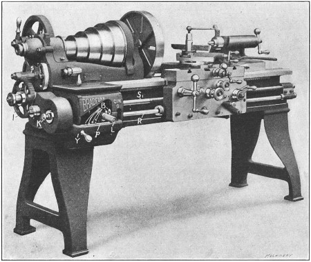
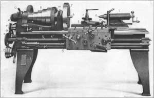
Fig. 30. Lathe having Quick Change-gear Mechanism
Quick Change-gear Type of Lathe.—A type of lathe that is
much used at the present time is shown in Fig. 30. This is
known as the quick change-gear type, because it has a system
of gearing which makes it unnecessary to remove the change
gears and replace them with different sizes for cutting threads
of various pitches. Changes of feed are also obtained by the
same mechanism, but the feeding movement is transmitted to
the carriage by the rod R, whereas the screw S1 is used for screw
cutting. As previously explained, the idea of using the screw exclusively
for threading is to prevent it from being worn excessively,
as it would be if continually used in place of rod R, for
feeding the carriage when turning.
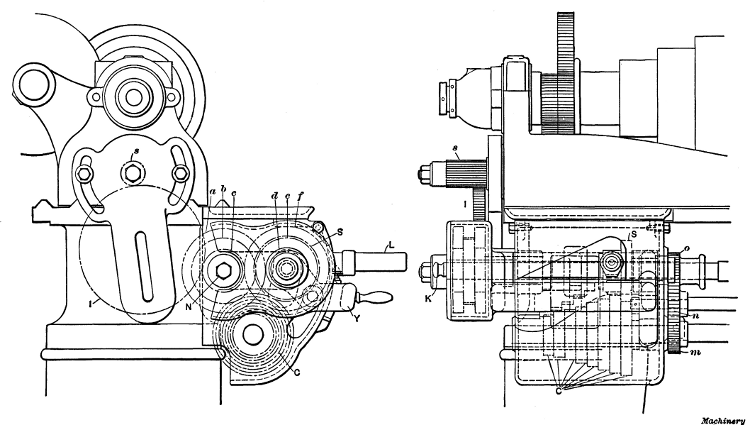
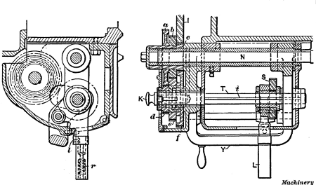
Fig. 31. End and Side Views of Quick Change-gear Mechanism
The general construction of this quick change gear mechanism and the
way the changes are made for cutting threads of different pitch, will be
explained in connection with Figs. 30, 31 and
32, which are marked with the same reference letters for corresponding
parts. Referring to Fig. 30, the movement is transmitted
from gear s on the spindle stud through idler gear I,
which can be moved sidewise to mesh with either of the three
gears a, b or c, Fig. 31. This cone of three gears engages gears
d, e and f, any one of which can be locked with shaft T (Fig.
32) by changing the position of knob K. On shaft T there is
a gear S which can be moved along the shaft by hand lever L
and, owing to the spline or key t, both the sliding gear and shaft
rotate together. Shaft T, carrying gears d, e and f and the
sliding gear S, is mounted in a yoke Y, which can be turned
about shaft N, thus making it possible to lower sliding gear S
into mesh with any one of a cone of eight gears C, Fig. 31. The
shaft on which the eight gears are mounted has at the end a
small gear m meshing with gear n on the feed-rod, and the latter,
in turn, drives the lead-screw, unless gear o is shifted to the
right out of engagement, which is its position except when
cutting threads.
Fig. 32. Sectional Views of Quick Change-gear Mechanism
With this mechanism, eight changes for different threads or
feeds are obtained by simply placing gear S into mesh with the various sized gears in cone C. As the speed of shaft T depends
on which of the three gears d, e and f are locked to it, the eight
changes are tripled by changing the position of knob K, making
twenty-four. Now by shifting idler gear I, three speed changes
may be obtained for gears a, b and c, which rotate together, so
that the twenty-four changes are also tripled, giving a total of
seventy-two variations without
removing any gears, and if a
different sized gear s were placed
on the spindle stud, an entirely
different range could be obtained,
but such a change would
rarely be necessary. As shown
in Fig. 30, there are eight hardened
steel buttons B, or one for
each gear of the cone C, placed
at different heights in the casing.
When lever L is shifted sidewise
to change the position of sliding
gear S, it is lowered onto one
of these buttons (which enters a
pocket on the under side) and in
this way gear S is brought into
proper mesh with any gear of the
cone C. To shift lever L, the
handle is pulled outward against
the tension of spring r (Fig. 32),
which disengages latch l and enables
the lever to be lifted clear of the button; yoke Y is then
raised or lowered, as the case may be, and lever L with the
sliding gear is shifted laterally to the required position.
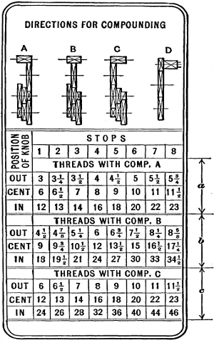
Fig. 33. Index Plate showing Position of Control Levers
for Cutting Threads of Different Pitch
The position of lever L and knob K for cutting threads of
different pitches is shown by an index plate or table attached
to the lathe and arranged as shown in Fig. 33. The upper
section a of this table shows the different numbers of threads to
the inch that can be obtained when idler gear I is in the position
shown by the diagram A. Section b gives the changes when the idler gear is moved, as shown at B, and, similarly, section
c gives the changes for position C of the idler. The horizontal
row of figures from 1 to 8 below the word “stops” represents
the eight positions for lever L, which has a plate p (Fig. 30) just
beneath it with corresponding numbers, and the column to the
left shows whether knob K should be out, in a central position,
or in.
In order to find what the position of lever L and knob K
should be for cutting any given number of threads to the inch,
find what “stop” number is directly above the number of threads
to be cut, which will indicate the location of lever L, and also what
position should be occupied by knob K, as shown in the column
to the left. For example, suppose the lathe is to be geared for
cutting eight threads to the inch. By referring to section a we
see that lever L should be in position 4 and knob K in the center,
provided the idler gear I were in position A, as it would be
ordinarily, because all standard numbers of threads per inch
(U. S. standard) from 1/4 inch up to and including 4 inches in
diameter can be cut with the idler gear in that position. As
another illustration, suppose we want to cut twenty-eight threads
per inch. This is listed in section c, which shows that lever L
must be placed in position 3 with knob K pushed in and the
idler gear shifted to the left as at C.
The simplicity of this method as compared with the time-consuming
operation of removing and changing gears is apparent.
The diagram D to the right shows an arrangement of
gearing for cutting nineteen threads per inch. A 20-tooth gear
is placed on the spindle stud (in place of the regular one having
16 teeth) and one with 95 teeth on the lead-screw, thus driving
the latter direct as with ordinary change gears. Of course it
will be understood that the arrangement of a quick change-gear
mechanism varies somewhat on lathes of different make.
Return to Contents